Arduino UNO R4 WiFi Controlled Smart Irrigation and Environmental Monitoring System
Circuit Documentation
Summary
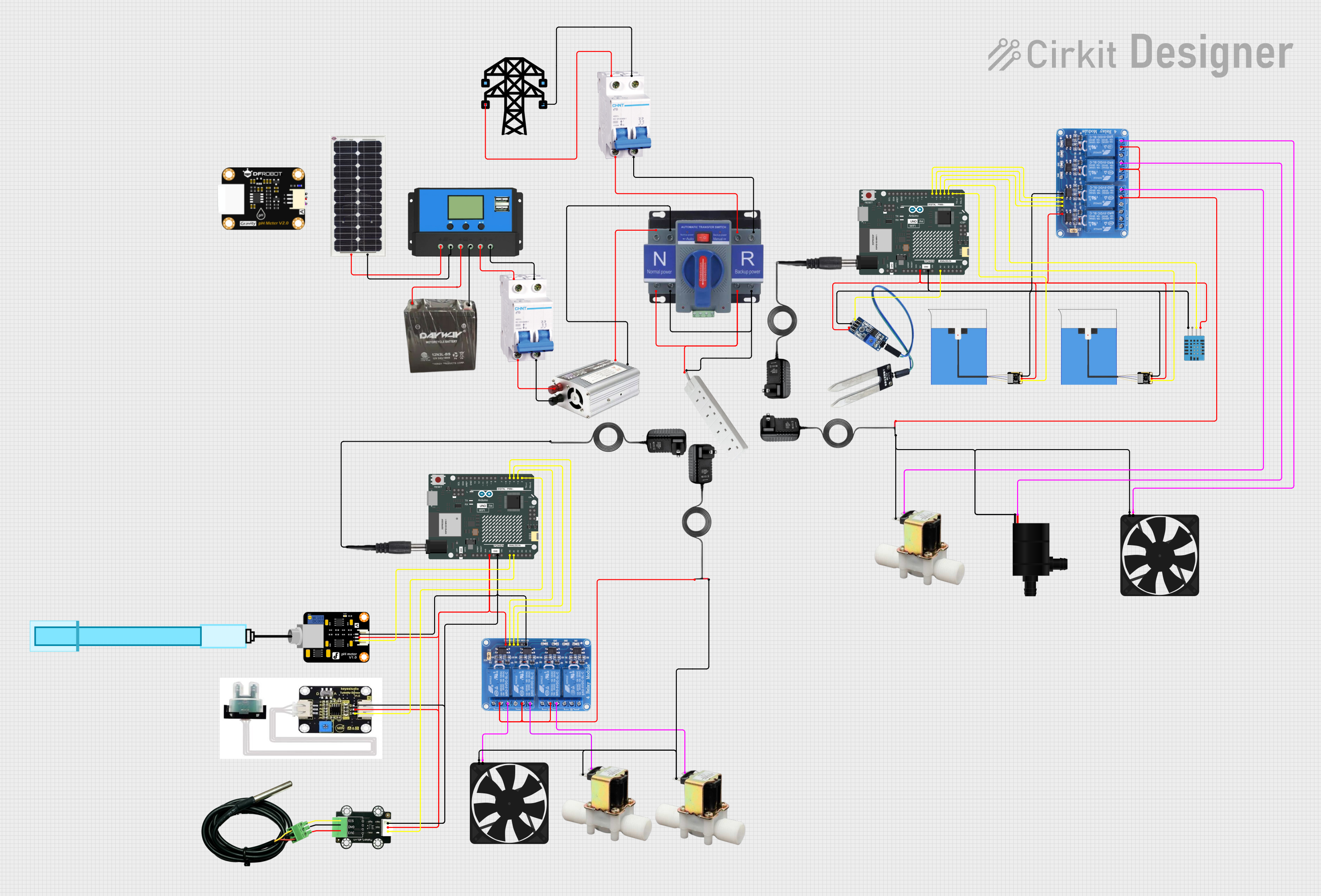
This circuit is designed to monitor and control various environmental parameters. It includes sensors for measuring soil moisture, humidity, temperature, turbidity, and pH levels. The system uses Arduino UNO R4 WiFi boards for processing sensor data and controlling devices like a water pump, fan, and electric valves. A solar charge controller is connected to a solar panel and a battery to provide a sustainable power source. The circuit also includes an ATS (Automatic Transfer Switch) and breakers for electrical safety and management. Relays are used to control high-power devices. The circuit is likely intended for an automated greenhouse or environmental monitoring system.
Component List
Microcontroller
- Arduino UNO R4 WiFi: A microcontroller board based on the ATmega328, with built-in WiFi capability. It has a variety of digital and analog I/O pins.
Sensors
- DHT11 Humidity and Temperature Sensor: Measures ambient humidity and temperature.
- Soil Moisture Sensor: Detects the moisture level in the soil.
- Turbidity Sensor: Measures the turbidity of a liquid, indicating how clear the liquid is.
- PH Meter: Measures the pH level of a liquid.
- MKE-S15 DS18B20 Waterproof Temperature Sensor: A waterproof temperature sensor for measuring liquid temperatures.
- Non-contact Liquid Level Sensors: Detects the presence or absence of a liquid without making contact with it.
Power Management
- Solar Charge Controller: Manages the power coming from solar panels to charge a battery and supply power to the circuit.
- Solar Panel: Converts sunlight into electrical energy.
- Battery (12V 3Ah): Stores electrical energy for use by the circuit.
Actuators
- Water Pump: Pumps water when activated.
- Fan: Provides air circulation when activated.
- Electric Valves: Controls the flow of liquids when activated.
Safety and Control
- ATS (Automatic Transfer Switch): Automatically switches power sources.
- Breakers: Protects the circuit from overcurrent.
- Towers: Likely refers to a structure or component that supports other components, but without more context, it's unclear.
Communication and Interface
- Relay 4 Channel 5V: Allows the Arduino to control higher power devices by providing isolation between the microcontroller and the device being controlled.
Miscellaneous
- Adapter: Used to adapt one type of electrical connector to another.
- Plug: Connects the circuit to an external power source.
- Socket: An outlet for connecting electrical devices.
- Dot: Likely a placeholder or reference point in the circuit, but without more context, it's unclear.
Wiring Details
Arduino UNO R4 WiFi
- 5V: Connected to sensors and relays requiring 5V power.
- GND: Common ground for the circuit.
- A0: Analog input connected to the soil moisture sensor.
- D2: Digital input connected to the non-contact liquid level sensor.
- D3: Digital input connected to another non-contact liquid level sensor.
- D4: Digital input connected to the DHT11 sensor for data communication.
- D5 - D7: Digital outputs connected to relay inputs for controlling various devices.
Sensors
DHT11 Humidity and Temperature Sensor
- VDD: 5V power supply.
- DATA: Connected to Arduino pin D4 for data communication.
- GND: Ground connection.
Soil Moisture Sensor
- Signal: Connected to Arduino pin A0 for moisture level reading.
Turbidity Sensor
- vin: 5V power supply from Arduino.
- GND: Ground connection.
- OUT: Analog output connected to Arduino pin A1.
PH Meter
- VCC: 5V power supply from Arduino.
- GND: Ground connection.
- Signal: Analog output connected to Arduino pin A0.
MKE-S15 DS18B20 Waterproof Temperature Sensor
- 5V: 5V power supply from Arduino.
- GND: Ground connection.
- SIG: Signal wire connected to Arduino pin D2.
Non-contact Liquid Level Sensors
- 5V: 5V power supply from Arduino.
- GND: Ground connection.
- OUT: Digital output connected to Arduino pins D2 and D3.
Power Management
- Solar Charge Controller
- Connected to the solar panel, battery, and breakers for managing the charging and power distribution.
Actuators
Water Pump
- VCC: Connected to a relay for power control.
- GND: Ground connection.
Fan
- 5V: Connected to a relay for power control.
- GND: Ground connection.
Electric Valves
- 12V: Connected to relays for power control.
- GND: Ground connection.
Safety and Control
ATS (Automatic Transfer Switch)
- Connected to the inverter, breakers, and sockets for automatic power source switching.
Breakers
- Connected to the solar charge controller, inverter, and ATS for circuit protection.
Communication and Interface
- Relay 4 Channel 5V
- VCC: 5V power supply from Arduino.
- GND: Ground connection.
- IN1 - IN4: Control inputs from Arduino digital pins D5 - D7 and D3.
- COM1 - COM4: Common terminals for relays.
- NC1 - NC4: Normally closed terminals for relays, connected to various actuators.
Documented Code
No code was provided for the microcontrollers in the circuit. The code would typically include the setup and loop functions, where the setup function initializes the pins and communication protocols, and the loop function contains the main logic for reading sensor data, processing it, and controlling the actuators based on the sensor inputs.