
Raspberry Pi Pico W-Based Voltage and Current Monitoring System with Wi-Fi Connectivity
View and Edit Project In Cirkit Designer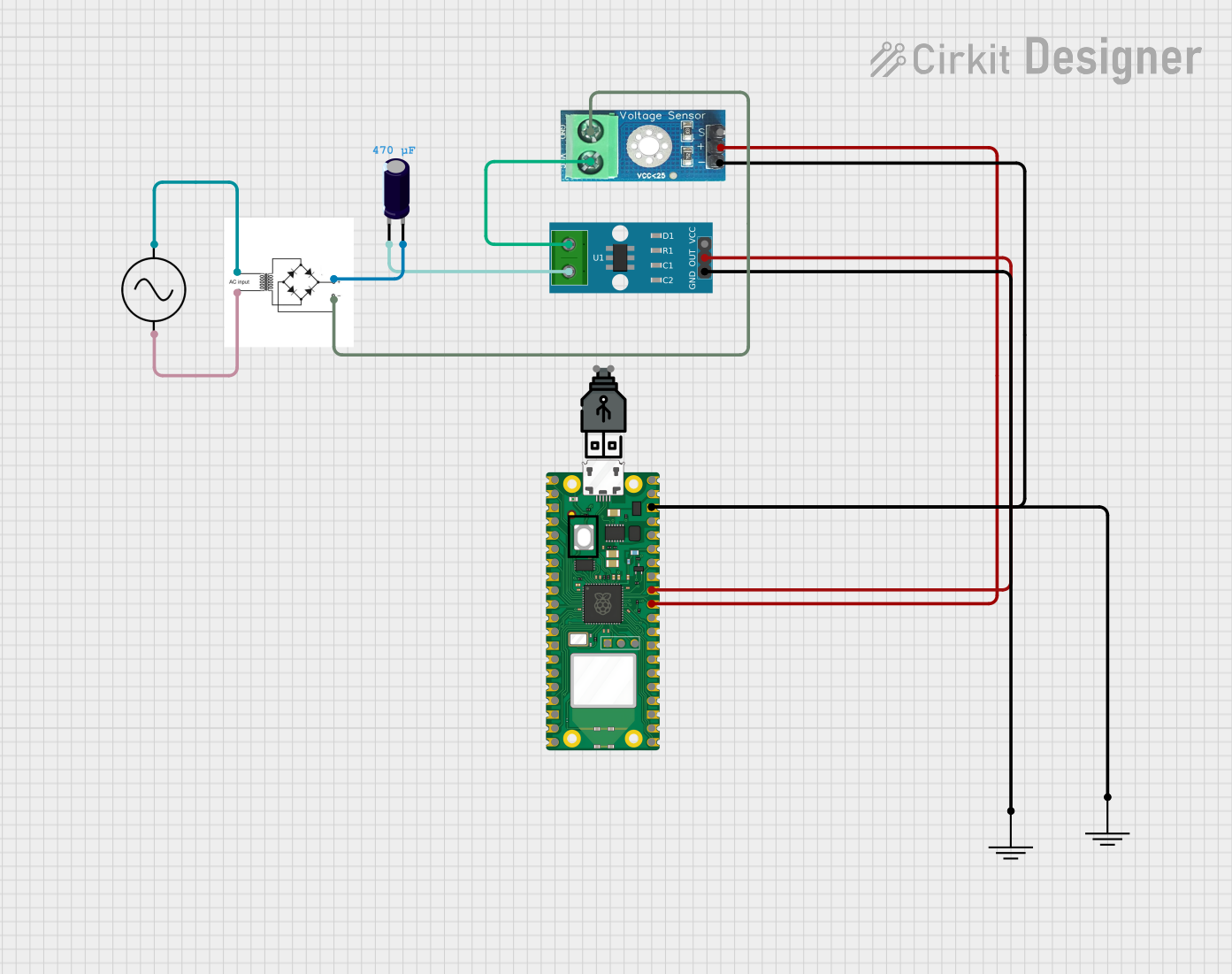
Circuit Documentation
Summary
This document provides a detailed overview of a circuit that includes a Raspberry Pi Pico W microcontroller, a voltage sensor, a current sensor, a bridge rectifier, an electrolytic capacitor, and an AC supply. The circuit is designed to measure voltage and current, and it includes a power supply and grounding components.
Component List
Raspberry Pi Pico W
- Description: A microcontroller board based on the Raspberry Pi RP2040 microcontroller chip.
- Pins: pin 1, pin 2, pin 3, pin 4, pin 5, pin 6, pin 7, pin 8, pin 9, pin 10, pin 11, pin 12, pin 13, pin 14, pin 15, pin 16, pin 17, pin 18, pin 19, pin 20, pin 21, pin 22, pin 23, pin 24, pin 25, pin 26, pin 27, pin 28, pin 29, pin 30, pin 31, pin 32, pin 33, pin 34, pin 35, pin 36, pin 37, pin 38, pin 39, pin 40, SWCLK, GND, SWDIO
Voltage Sensor DC 25V
- Description: A sensor used to measure DC voltage up to 25V.
- Pins: +, -, output, gnd, vcc
ACS712 Current Sensor 5A 20A 30A
- Description: A sensor used to measure current in the range of 5A, 20A, or 30A.
- Pins: 1, 2, GND, OUT, VCC
GND
- Description: Ground connection.
- Pins: GND
USB Power
- Description: Provides power to the circuit via USB.
- Pins: +, -
Bridge Rectifier
- Description: Converts AC input to DC output.
- Pins: AC input +, AC input -, +, -
AC Supply
- Description: Provides AC power to the circuit.
- Pins: +ve, -ve
Electrolytic Capacitor
- Description: A capacitor used to smooth out voltage fluctuations.
- Pins: -, +
- Properties:
- Capacitance: 0.00047 Farads
Wiring Details
Raspberry Pi Pico W
- pin 31 is connected to Voltage Sensor DC 25V pin +
- pin 32 is connected to ACS712 Current Sensor 5A 20A 30A pin OUT
- pin 38 is connected to GND pin GND and Voltage Sensor DC 25V pin -
Voltage Sensor DC 25V
- + is connected to Raspberry Pi Pico W pin 31
- - is connected to GND pin GND and Raspberry Pi Pico W pin 38
- gnd is connected to Bridge Rectifier pin -
- vcc is connected to ACS712 Current Sensor 5A 20A 30A pin 1
ACS712 Current Sensor 5A 20A 30A
- OUT is connected to Raspberry Pi Pico W pin 32
- 1 is connected to Voltage Sensor DC 25V pin vcc
- 2 is connected to Electrolytic Capacitor pin -
- GND is connected to GND pin GND
GND
- GND is connected to Raspberry Pi Pico W pin 38 and Voltage Sensor DC 25V pin -
- GND is connected to ACS712 Current Sensor 5A 20A 30A pin GND
Bridge Rectifier
- - is connected to Voltage Sensor DC 25V pin gnd
- AC input + is connected to AC Supply pin +ve
- AC input - is connected to AC Supply pin -ve
- + is connected to Electrolytic Capacitor pin +
AC Supply
- +ve is connected to Bridge Rectifier pin AC input +
- -ve is connected to Bridge Rectifier pin AC input -
Electrolytic Capacitor
- - is connected to ACS712 Current Sensor 5A 20A 30A pin 2
- + is connected to Bridge Rectifier pin +
Documented Code
Raspberry Pi Pico W Code
void setup() {
  // put your setup code here, to run once:

}

void loop() {
  // put your main code here, to run repeatedly:

}
This code is a basic template for the Raspberry Pi Pico W microcontroller. The setup function is where you initialize your microcontroller, and the loop function is where you place the code that you want to run repeatedly.