
Arduino UNO-Based Motion-Activated Alarm System with LED Indicator and Piezo Buzzer
View and Edit Project In Cirkit Designer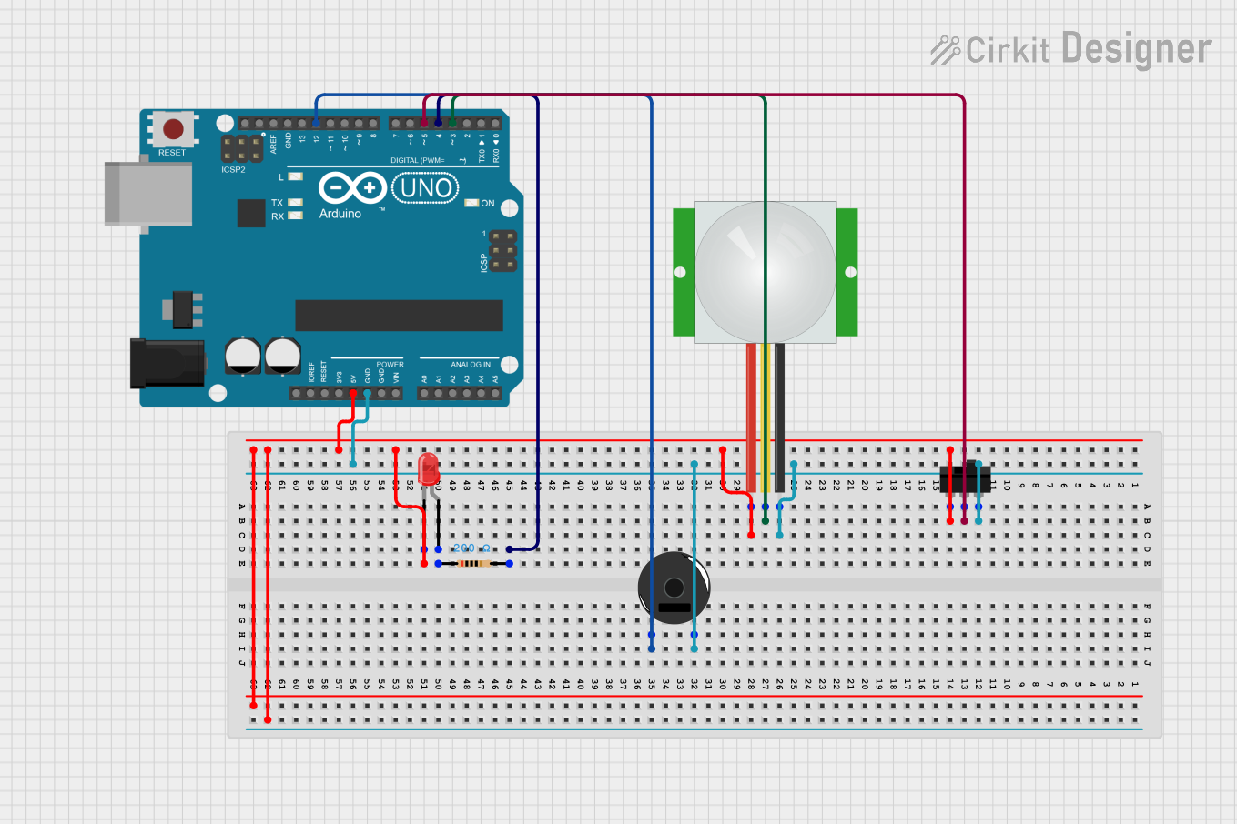
Circuit Documentation
Summary
This circuit is designed to use a PIR sensor and a toggle switch to control an LED and a piezo buzzer using an Arduino UNO. When both the PIR sensor detects motion and the toggle switch is activated, the LED lights up and the buzzer sounds for a specified duration.
Component List
Arduino UNO
- Description: A microcontroller board based on the ATmega328P.
- Pins: UNUSED, IOREF, Reset, 3.3V, 5V, GND, Vin, A0, A1, A2, A3, A4, A5, SCL, SDA, AREF, D13, D12, D11, D10, D9, D8, D7, D6, D5, D4, D3, D2, D1, D0
LED: Two Pin (red)
- Description: A red LED with two pins.
- Pins: cathode, anode
Resistor
- Description: A resistor with a resistance of 200 Ohms.
- Pins: pin1, pin2
- Properties:
- Resistance: 200 Ohms
PIR sensor
- Description: A passive infrared sensor used to detect motion.
- Pins: VDD, SIG, GND
Toggle Switch
- Description: A switch with three pins.
- Pins: L1, COM, L2
Piezo Buzzer
- Description: A piezoelectric buzzer with two pins.
- Pins: pin 1, pin 2
Wiring Details
Arduino UNO
GND is connected to:
- Toggle Switch (L2)
- PIR sensor (GND)
- Piezo Buzzer (pin 2)
5V is connected to:
- Toggle Switch (L1)
- PIR sensor (VDD)
- LED (cathode)
D3 is connected to:
- PIR sensor (SIG)
D4 is connected to:
- Resistor (pin2)
D5 is connected to:
- Toggle Switch (COM)
D12 is connected to:
- Piezo Buzzer (pin 1)
LED: Two Pin (red)
cathode is connected to:
- Arduino UNO (5V)
- Toggle Switch (L1)
- PIR sensor (VDD)
anode is connected to:
- Resistor (pin1)
Resistor
pin1 is connected to:
- LED (anode)
pin2 is connected to:
- Arduino UNO (D4)
PIR sensor
VDD is connected to:
- Toggle Switch (L1)
- Arduino UNO (5V)
- LED (cathode)
SIG is connected to:
- Arduino UNO (D3)
GND is connected to:
- Toggle Switch (L2)
- Arduino UNO (GND)
- Piezo Buzzer (pin 2)
Toggle Switch
L1 is connected to:
- PIR sensor (VDD)
- Arduino UNO (5V)
- LED (cathode)
COM is connected to:
- Arduino UNO (D5)
L2 is connected to:
- PIR sensor (GND)
- Arduino UNO (GND)
- Piezo Buzzer (pin 2)
Piezo Buzzer
pin 1 is connected to:
- Arduino UNO (D12)
pin 2 is connected to:
- Toggle Switch (L2)
- PIR sensor (GND)
- Arduino UNO (GND)
Code Documentation
Arduino UNO Code
const int led = 4;
int pir = 3;
int holderpir = 0;
int slide = 5;
int holderslide = 0;
int buzzer = 12;

void setup() {
    pinMode(led, OUTPUT);
    pinMode(pir, INPUT);
    pinMode(slide, INPUT);
    pinMode(buzzer, OUTPUT);
}

void loop() {
    holderpir = digitalRead(pir);
    holderslide = digitalRead(slide);

    if (holderslide == 1 & holderpir == 1) {
        digitalWrite(led, HIGH);
        analogWrite(buzzer, 255);
        delay(10000);
    }
    digitalWrite(led, LOW);
    analogWrite(buzzer, 0);
}
This code initializes the pins for the LED, PIR sensor, toggle switch, and piezo buzzer. In the main loop, it reads the state of the PIR sensor and the toggle switch. If both are activated, it turns on the LED and the buzzer for 10 seconds. After that, it turns off the LED and the buzzer.