
ESP32-S3 GPS Logger and Wind Speed Display with Dual OLED and CAN Bus
View and Edit Project In Cirkit Designer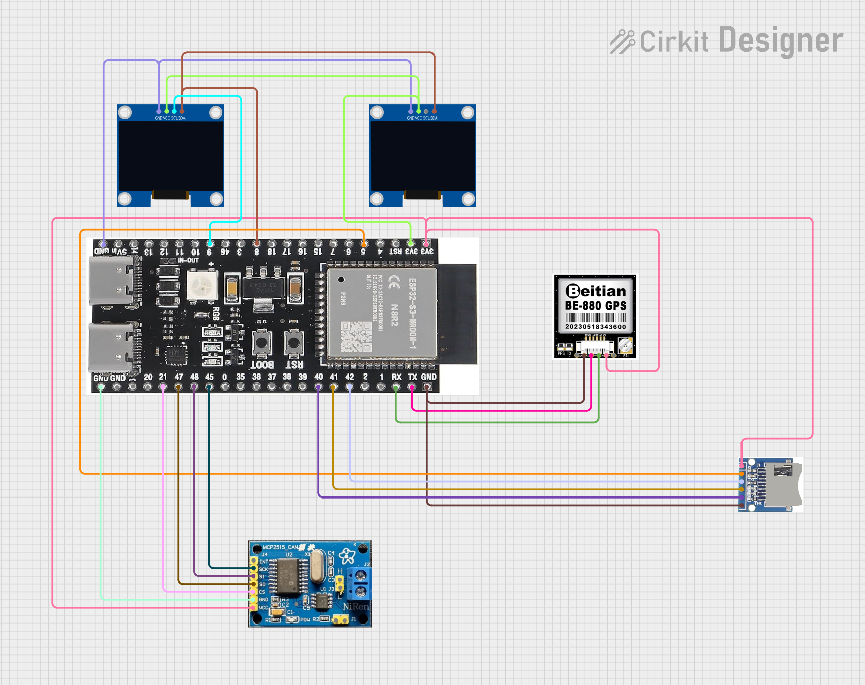
Circuit Documentation
Summary
This circuit is designed around an ESP32-S3-DevKitC-1-N8R2 microcontroller. It interfaces with various peripherals including an SD card module, two OLED displays, a CAN bus module, and a GPS module. The primary functions of the circuit are to record GPS data to an SD card every second, display speed in knots on the first OLED display, and display wind speed from the CAN bus in NMEA 2000 format on the second OLED display.
Component List
ESP32-S3-DevKitC-1-N8R2
- Description: A powerful microcontroller with Wi-Fi and Bluetooth capabilities.
- Pins: GND, 5Vin, 14, 13, 12, 11, 10, 9, 46, 3, 8, 18, 17, 16, 15, 7, 6, 5, 4, 3v3, TX, RX, 1, 2, 42, 41, 40, 39, 38, 37, 36, 35, 0, 45, 48, 47, 21, 20, 19
BE - 880
- Description: A GPS module.
- Pins: GND, VCC, SDA, TX, RX, SCL
SD SDHC
- Description: An SD card module for data storage.
- Pins: 3V3, CS, MOSI, CLK, MISO, GND
128x64 OLED Display (I2C IIC SPI Serial)
- Description: A 128x64 pixel OLED display.
- Pins: GND, SDA, SCL, VCC
CAN BUS
- Description: A CAN bus module for communication.
- Pins: INT, SCK, SI, SO, CS, GND, VCC, J1, J11, H, L, VDD
Wiring Details
ESP32-S3-DevKitC-1-N8R2
- GND: Connected to GND of both OLED displays, CAN bus module, BE - 880, and SD SDHC.
- 3v3: Connected to VCC of both OLED displays, CAN bus module, BE - 880, and SD SDHC.
- 5: Connected to CS of SD SDHC.
- 8: Connected to SDA of both OLED displays.
- 9: Connected to SCL of the first OLED display.
- 21: Connected to CS of CAN bus module.
- 40: Connected to MISO of SD SDHC.
- 41: Connected to CLK of SD SDHC.
- 42: Connected to MOSI of SD SDHC.
- 45: Connected to SCK of CAN bus module.
- 47: Connected to SO of CAN bus module.
- 48: Connected to SI of CAN bus module.
- TX: Connected to TX of BE - 880.
- RX: Connected to RX of BE - 880.
BE - 880
- GND: Connected to GND of ESP32-S3-DevKitC-1-N8R2.
- VCC: Connected to 3v3 of ESP32-S3-DevKitC-1-N8R2.
- TX: Connected to TX of ESP32-S3-DevKitC-1-N8R2.
- RX: Connected to RX of ESP32-S3-DevKitC-1-N8R2.
SD SDHC
- 3V3: Connected to 3v3 of ESP32-S3-DevKitC-1-N8R2.
- CS: Connected to 5 of ESP32-S3-DevKitC-1-N8R2.
- MOSI: Connected to 42 of ESP32-S3-DevKitC-1-N8R2.
- CLK: Connected to 41 of ESP32-S3-DevKitC-1-N8R2.
- MISO: Connected to 40 of ESP32-S3-DevKitC-1-N8R2.
- GND: Connected to GND of ESP32-S3-DevKitC-1-N8R2.
128x64 OLED Display (I2C IIC SPI Serial) - First Display
- GND: Connected to GND of ESP32-S3-DevKitC-1-N8R2.
- SDA: Connected to 8 of ESP32-S3-DevKitC-1-N8R2.
- SCL: Connected to 9 of ESP32-S3-DevKitC-1-N8R2.
- VCC: Connected to 3v3 of ESP32-S3-DevKitC-1-N8R2.
128x64 OLED Display (I2C IIC SPI Serial) - Second Display
- GND: Connected to GND of ESP32-S3-DevKitC-1-N8R2.
- SDA: Connected to 8 of ESP32-S3-DevKitC-1-N8R2.
- SCL: Connected to 9 of ESP32-S3-DevKitC-1-N8R2.
- VCC: Connected to 3v3 of ESP32-S3-DevKitC-1-N8R2.
CAN BUS
- GND: Connected to GND of ESP32-S3-DevKitC-1-N8R2.
- VCC: Connected to 3v3 of ESP32-S3-DevKitC-1-N8R2.
- SCK: Connected to 45 of ESP32-S3-DevKitC-1-N8R2.
- SI: Connected to 48 of ESP32-S3-DevKitC-1-N8R2.
- SO: Connected to 47 of ESP32-S3-DevKitC-1-N8R2.
- CS: Connected to 21 of ESP32-S3-DevKitC-1-N8R2.
Code Documentation
/*
 * This Arduino Sketch is for an ESP32-S3-DevKitC-1-N8R2 connected to various
 * peripherals. It records GPS position to an SD card every second, displays
 * speed in knots on the first OLED display, and displays wind speed from the
 * CAN bus in NMEA 2000 format on the second OLED display.
 */

#include <Wire.h>
#include <SPI.h>
#include <SD.h>
#include <Adafruit_GFX.h>
#include <Adafruit_SSD1306.h>
#include <CAN.h>

// Pin definitions
#define SD_CS 5
#define OLED1_SDA 8
#define OLED1_SCL 9
#define OLED2_SDA 8
#define OLED2_SCL 9
#define CAN_CS 21
#define CAN_SCK 45
#define CAN_MISO 47
#define CAN_MOSI 48

// OLED display objects
Adafruit_SSD1306 display1(128, 64, &Wire, -1);
Adafruit_SSD1306 display2(128, 64, &Wire, -1);

// GPS data
String gpsData = "";

void setup() {
  // Initialize serial communication
  Serial.begin(115200);
  while (!Serial);
  Serial.println("Starting...");

  // Initialize SD card
  if (!SD.begin(SD_CS)) {
    Serial.println("SD card initialization failed!");
    while (1);
  }

  // Initialize OLED displays
  Wire.begin(OLED1_SDA, OLED1_SCL);
  if (!display1.begin(SSD1306_SWITCHCAPVCC, 0x3C)) {
    Serial.println("OLED1 initialization failed!");
    while (1);
  }
  if (!display2.begin(SSD1306_SWITCHCAPVCC, 0x3D)) {
    Serial.println("OLED2 initialization failed!");
    while (1);
  }
  display1.clearDisplay();
  display2.clearDisplay();

  // Initialize CAN bus
  CAN.setPins(CAN_CS, CAN_MISO, CAN_MOSI, CAN_SCK); // Move this line before CAN.begin()
  if (!CAN.begin(500E3)) {
    Serial.println("CAN bus initialization failed!");
    while (1);
  }
}

void loop() {
  // Record GPS data to SD card
  File dataFile = SD.open("gps.txt", FILE_WRITE);
  if (dataFile) {
    dataFile.println(gpsData);
    dataFile.close();
  } else {
    Serial.println("Error opening gps.txt");
  }

  // Display speed in knots on OLED1
  display1.clearDisplay();
  display1.setTextSize(1);
  display1.setTextColor(SSD1306_WHITE);
  display1.setCursor(0, 0);
  display1.print("Speed: ");
  display1.print(getSpeedInKnots());
  display1.print(" knots");
  display1.display();

  // Display wind speed from CAN bus on OLED2
  display2.clearDisplay();