Cirkit Designer
Your all-in-one circuit design IDE
Home /
Project Documentation
Arduino UNO Based Air Quality Monitoring and GSM Notification System

Circuit Documentation
Summary of the Circuit
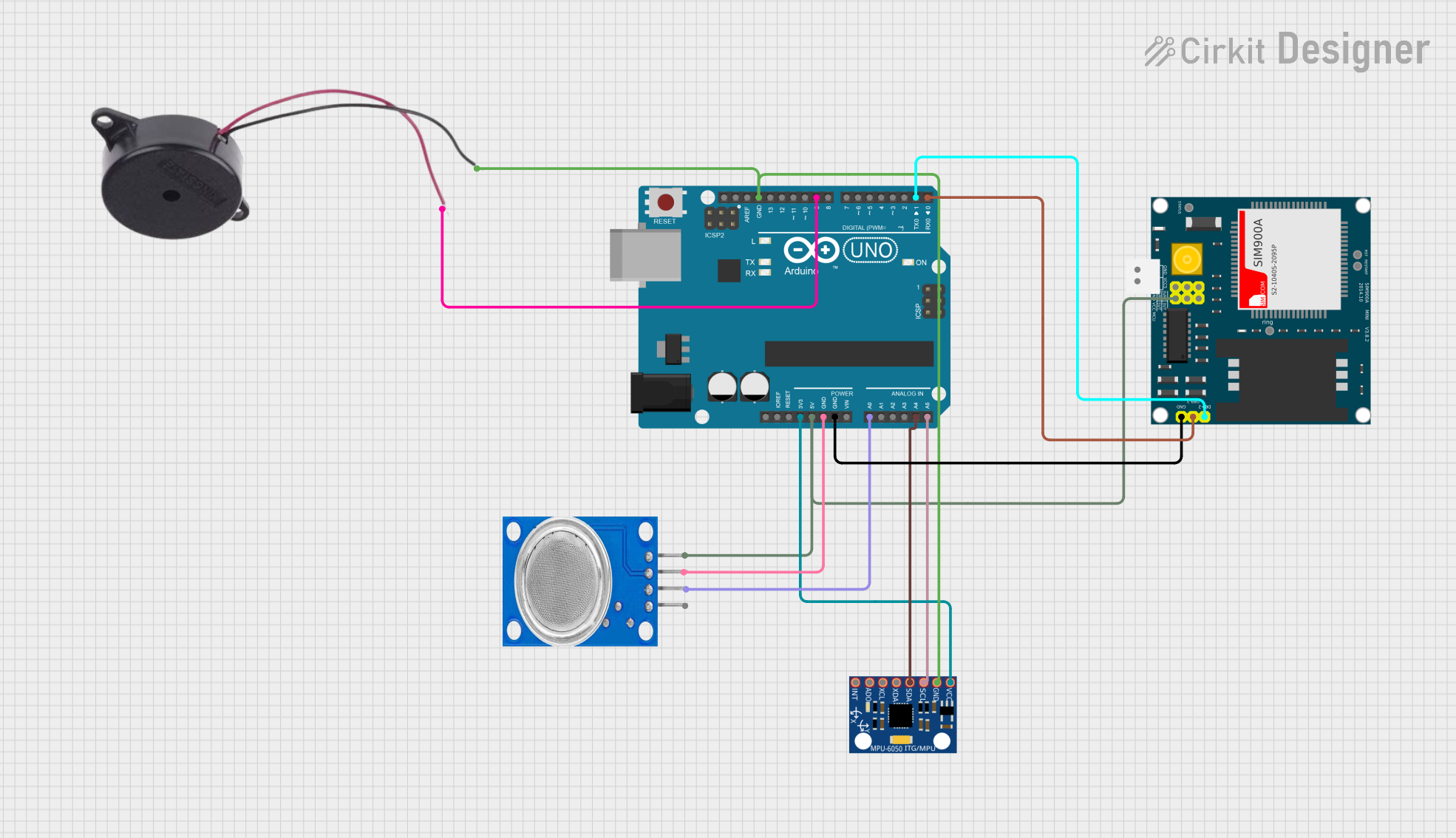
This circuit integrates an Arduino UNO microcontroller with several peripheral components to perform various functions. The Arduino UNO serves as the central processing unit, interfacing with an MQ135 air quality sensor, a buzzer, a SIM900A GSM module, and an MPU-6050 accelerometer and gyroscope module. The circuit is designed to monitor air quality and motion, and it can communicate with external systems via the GSM module. The buzzer provides an audible alert mechanism.
Component List
Arduino UNO
- Microcontroller board based on the ATmega328P
- It has 14 digital input/output pins, 6 analog inputs, a 16 MHz quartz crystal, a USB connection, a power jack, an ICSP header, and a reset button.
MQ135
- Air quality sensor for detecting a wide range of gases, including NH3, NOx, alcohol, benzene, smoke, and CO2.
Buzzer
- An electromechanical component that produces an audible tone when energized.
SIM900A
- GSM/GPRS module that can be used for SMS, data, and voice communication.
MPU-6050
- Motion tracking device that contains a MEMS accelerometer and a MEMS gyro in a single chip. It is very accurate, as it contains 16-bits analog to digital conversion hardware for each channel.
Wiring Details
Arduino UNO
- 3.3V connected to MPU-6050 VCC
- 5V connected to MQ135 VCC and SIM900A VCC
- GND connected to MQ135 GND, SIM900A GND, MPU-6050 GND, and Buzzer NEGATIVE
- A0 connected to MQ135 A0
- A4 (SDA) connected to MPU-6050 SDA
- A5 (SCL) connected to MPU-6050 SCL
- D9 connected to Buzzer POSITIVE
- D1 (TX) connected to SIM900A DB9-2 (TXD)
- D0 (RX) connected to SIM900A DB9-3 (RXD)
MQ135
- VCC connected to Arduino UNO 5V
- GND connected to Arduino UNO GND
- A0 connected to Arduino UNO A0
Buzzer
- POSITIVE connected to Arduino UNO D9
- NEGATIVE connected to Arduino UNO GND
SIM900A
- VCC connected to Arduino UNO 5V
- GND connected to Arduino UNO GND
- DB9-3 (RXD) connected to Arduino UNO D0 (RX)
- DB9-2 (TXD) connected to Arduino UNO D1 (TX)
MPU-6050
- VCC connected to Arduino UNO 3.3V
- GND connected to Arduino UNO GND
- SCL connected to Arduino UNO A5 (SCL)
- SDA connected to Arduino UNO A4 (SDA)
Documented Code
Arduino UNO Code (sketch.ino)
void setup() {
  // put your setup code here, to run once:

}

void loop() {
  // put your main code here, to run repeatedly:

}
Note: The code provided is a template and does not include specific functionality. It should be populated with the setup and loop code required to initialize and control the connected components.