Raspberry Pi 5 and ESP32-Based Smart Environmental Monitoring System with NFC/RFID and Access Control
Circuit Documentation
Summary
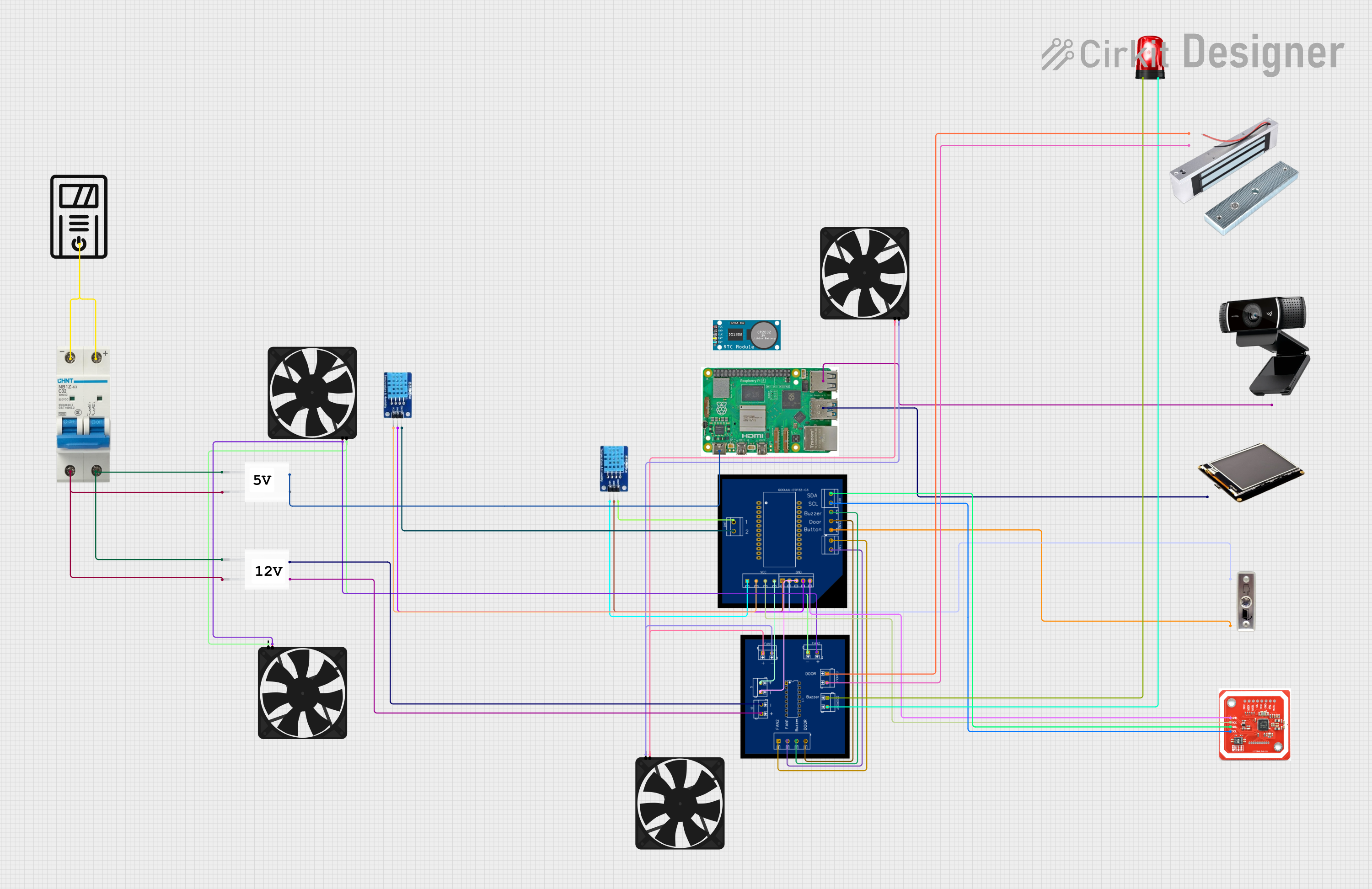
The circuit described in the provided inputs is a complex system that includes a power supply, a Raspberry Pi 5, multiple fans, sensors, a display, an NFC/RFID reader, a real-time clock (RTC), a webcam, a siren, a button switch for a door, a magnetic lock, an ESP32 PCB for control and interfacing, an IC switch for power management, and a UPS for uninterrupted power supply. The circuit is designed to be powered by a 5V adapter and includes a circuit breaker for protection. The Raspberry Pi 5 serves as the central processing unit, interfacing with various peripherals like the display, webcam, and sensors. The ESP32 PCB is used for additional control and interfacing with components like the DHT11 temperature and humidity sensors, NFC/RFID reader, fans, and the magnetic lock. The IC switch manages power distribution to the various components.
Component List
Power Supply
- 5V Adapter: Converts AC to a 5V DC output.
Processing Units
- Raspberry Pi 5: A single-board computer with multiple I/O options.
- ESP32 PCB: A microcontroller board for interfacing and controlling various peripherals.
Sensors
- DHT11: Temperature and humidity sensor.
- NFC/RFID reader: A sensor for reading NFC and RFID tags.
- RTC: Real-time clock for timekeeping.
Actuators
- Fan: Used for cooling.
- Siren: An audible alarm device.
- Magnetic lock: An electromagnetic lock for securing doors.
Input/Output Devices
- TFT Raspberry Pi: A display screen for the Raspberry Pi.
- Webcam: A USB camera for video input.
- Button Switch door: A button used as a door switch.
Power Management
- UPS: Uninterruptible power supply for backup power.
- Circuit Breaker: A safety device to prevent overcurrent.
Miscellaneous
- IC switch: An integrated circuit used for switching power lines.
Wiring Details
5V Adapter
- Provides 5V and GND to the IC switch and Raspberry Pi 5.
Raspberry Pi 5
- Receives power from the 5V Adapter.
- USB 3.0 connected to the TFT Raspberry Pi.
- USB 2.0 connected to the webcam.
Fans
- Multiple fans connected to the IC switch for power control.
DHT11 Sensors
- Two instances of DHT11 sensors interfaced with the ESP32 PCB for temperature and humidity readings.
NFC/RFID Reader
- Powered and interfaced with the ESP32 PCB for reading NFC/RFID tags.
RTC
- Real-time clock module (details of connections not provided).
Webcam
- Connected to the Raspberry Pi 5 via USB 2.0.
Siren
- Connected to the IC switch for activation control.
Button Switch Door
- Interfaced with the ESP32 PCB to act as a door switch.
Magnetic Lock
- Powered and controlled via the IC switch.
UPS
- Provides backup power (details of connections not provided).
Circuit Breaker
- Connected to the UPS and 5V Adapters for overcurrent protection.
IC Switch
- Manages power distribution to the fans, siren, magnetic lock, and ESP32 PCB.
Documented Code
No code was provided in the input. Therefore, this section is not applicable to the current documentation.
Please note that the documentation above is based on the provided inputs. For a complete and accurate representation of the circuit, additional details such as the purpose of each part in the circuit, specific wiring instructions, and actual embedded code for the microcontrollers would be necessary.