
Solar-Powered Battery Charging System with Voltage Display and Regulation
View and Edit Project In Cirkit Designer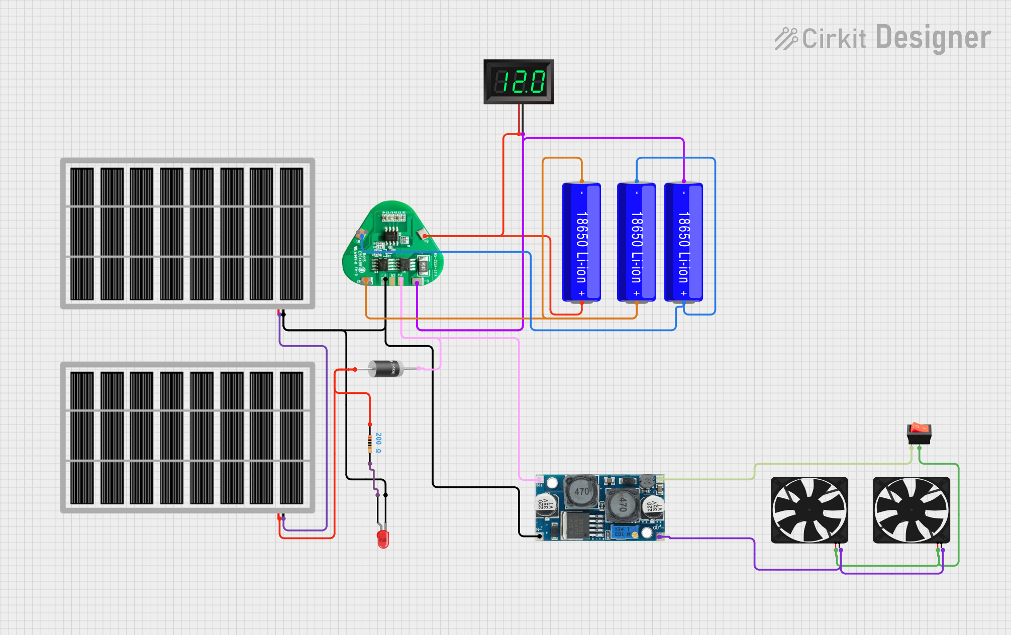
Circuit Documentation
Summary of the Circuit
This circuit appears to be a solar-powered system with energy storage and voltage regulation capabilities. It includes solar panels for energy harvesting, 18650 Li-ion batteries for energy storage, a voltage regulator to maintain a stable output voltage, and a battery management system (BMS) to protect the batteries. Additionally, the circuit features a 7-segment panel voltmeter for voltage display, LEDs for indication, diodes for current direction control, and fans for cooling. A rocker switch is used to control the power to the fans.
Component List
Solar Panels
- Description: Photovoltaic panels used to convert sunlight into electrical energy.
- Pins: Ground (gnd), Voltage out (vcc)
18650 Li-ion Batteries
- Description: Rechargeable batteries used for energy storage.
- Pins: Negative (-), Positive (+)
7-Segment Panel Voltmeter
- Description: A display used for showing the voltage level.
- Pins: Voltage positive (V+), Voltage negative (V-)
Resistor
- Description: A passive two-terminal electrical component that implements electrical resistance as a circuit element.
- Resistance: 200 Ohms
LED: Two Pin (red)
- Description: A red light-emitting diode used as an indicator.
- Pins: Cathode, Anode
5408 Diode
- Description: A diode used for ensuring current flows in one direction.
- Pins: Cathode, Anode
XL6009 Voltage Regulator
- Description: A DC-DC voltage regulator used to maintain a stable output voltage.
- Pins: Output positive (OUT +), Output negative (OUT -), Input positive (IN +), Input negative (IN -)
Fans
- Description: Cooling devices powered by the circuit.
- Pins: Ground (GND), Voltage in (5V)
Rocker Switch
- Description: A switch used to control the connection of the circuit.
- Pins: Output, Input
BMS 3S
- Description: A battery management system used for protecting the Li-ion batteries.
- Pins: Positive (+), Negative (-)
Wiring Details
Solar Panels
- Ground (gnd) connected to the ground of the circuit.
- Voltage out (vcc) connected to the diode and resistor.
18650 Li-ion Batteries
- Negative (-) connected to the BMS and the 7-segment panel voltmeter.
- Positive (+) connected to the BMS and other batteries in series/parallel as required.
7-Segment Panel Voltmeter
- Voltage positive (V+) connected to the BMS positive.
- Voltage negative (V-) connected to the BMS negative.
Resistor
- One pin connected to the solar panel vcc.
- Other pin connected to the LED anode.
LED: Two Pin (red)
- Cathode connected to the solar panel ground.
- Anode connected to the resistor.
5408 Diode
- Cathode connected to the voltage regulator input.
- Anode connected to the solar panel vcc.
XL6009 Voltage Regulator
- Output positive (OUT +) connected to the rocker switch input.
- Output negative (OUT -) connected to the ground of the fans.
- Input positive (IN +) connected to the diode.
- Input negative (IN -) connected to the ground of the circuit.
Fans
- Ground (GND) connected to the voltage regulator output negative.
- Voltage in (5V) connected to the rocker switch output.
Rocker Switch
- Output connected to the fans' voltage in.
- Input connected to the voltage regulator output positive.
BMS 3S
- Positive (+) connected to the batteries and the 7-segment panel voltmeter.
- Negative (-) connected to the batteries and the 7-segment panel voltmeter.
Documented Code
No microcontroller code has been provided for this circuit. If there is a need for control logic or data processing, a microcontroller or other programmable device would be included, and the corresponding code would be documented in this section.