
Raspberry Pi 3B-Based Ultrasonic Distance Measurement System with Serial JPEG Camera Integration
View and Edit Project In Cirkit Designer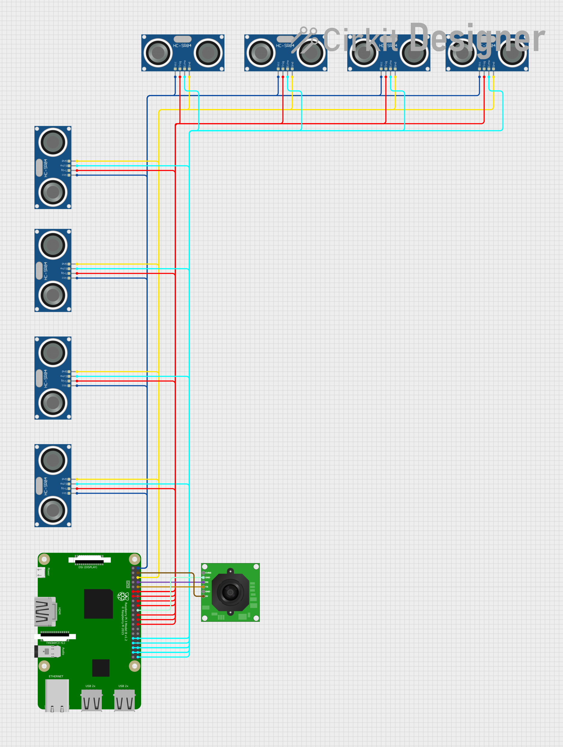
Circuit Documentation
Summary
The circuit in question is designed to interface multiple HC-SR04 Ultrasonic Sensors with a Raspberry Pi 3B for the purpose of distance measurement. Additionally, a TTL Serial JPEG Camera is included in the circuit for capturing images. The Raspberry Pi 3B serves as the central processing unit, controlling the ultrasonic sensors and communicating with the camera. The ultrasonic sensors are used to trigger distance measurements and receive echo signals, which are then processed by the Raspberry Pi to determine the distance to an object. The camera is interfaced via serial communication for image capture.
Component List
Raspberry Pi 3B
- Description: A single-board computer with GPIO pins used for interfacing with various sensors and modules.
- Pins: 3v3, GPIO2, GPIO3, GPIO4, GND, GPIO17, GPIO27, GPIO22, 3V3, GPIO10, GPIO9, GPIO11, ID_SD, GPIO5, GPIO6, GPIO13, GPIO19, GPIO26, GPIO21, GPIO20, GPIO16, GPIO12, ID_SC, GPIO7, GPIO8, GPIO25, GPIO24, GPIO23, GPIO18, GPIO15, GPIO14, 5V
HC-SR04 Ultrasonic Sensor
- Description: An ultrasonic distance sensor that uses sonar to determine the distance to an object.
- Pins: VCC, TRIG, ECHO, GND
TTL Serial JPEG Camera
- Description: A camera module that captures JPEG images and sends them over a serial connection.
- Pins: GND, RX, TX, CVBS, 5V
Wiring Details
Raspberry Pi 3B
- GPIO17 connected to HC-SR04 Ultrasonic Sensor TRIG
- GPIO27 connected to HC-SR04 Ultrasonic Sensor TRIG
- GPIO6 connected to HC-SR04 Ultrasonic Sensor ECHO
- GPIO13 connected to HC-SR04 Ultrasonic Sensor ECHO
- GPIO19 connected to HC-SR04 Ultrasonic Sensor ECHO
- GPIO26 connected to HC-SR04 Ultrasonic Sensor ECHO
- GPIO21 connected to HC-SR04 Ultrasonic Sensor ECHO
- GPIO20 connected to HC-SR04 Ultrasonic Sensor ECHO
- GPIO16 connected to HC-SR04 Ultrasonic Sensor ECHO
- GPIO12 connected to HC-SR04 Ultrasonic Sensor ECHO
- GPIO7 connected to HC-SR04 Ultrasonic Sensor TRIG
- GPIO8 connected to HC-SR04 Ultrasonic Sensor TRIG
- GPIO25 connected to HC-SR04 Ultrasonic Sensor TRIG
- GND connected to TTL Serial JPEG Camera GND and all HC-SR04 Ultrasonic Sensor GND pins
- GPIO24 connected to HC-SR04 Ultrasonic Sensor TRIG
- GPIO23 connected to HC-SR04 Ultrasonic Sensor TRIG
- GPIO18 connected to HC-SR04 Ultrasonic Sensor TRIG
- GPIO15 connected to TTL Serial JPEG Camera RX
- GPIO14 connected to TTL Serial JPEG Camera TX
- 5V connected to TTL Serial JPEG Camera 5V and all HC-SR04 Ultrasonic Sensor VCC pins
HC-SR04 Ultrasonic Sensor
- VCC connected to Raspberry Pi 3B 5V
- TRIG connected to specific GPIO pins on Raspberry Pi 3B
- ECHO connected to specific GPIO pins on Raspberry Pi 3B
- GND connected to Raspberry Pi 3B GND
TTL Serial JPEG Camera
- GND connected to Raspberry Pi 3B GND
- RX connected to Raspberry Pi 3B GPIO15
- TX connected to Raspberry Pi 3B GPIO14
- 5V connected to Raspberry Pi 3B 5V
Documented Code
No code has been provided for the microcontrollers in the circuit. The code would typically include initialization of GPIO pins, handling of the ultrasonic sensor signals, and communication with the camera module. It would also contain the main logic for triggering the sensors, reading the echo signals, calculating distances, capturing images, and possibly communicating the data to an external system or storing it locally.