
Arduino UNO-Based Solar-Powered Motion Detection and Alert System with GSM Module
View and Edit Project In Cirkit Designer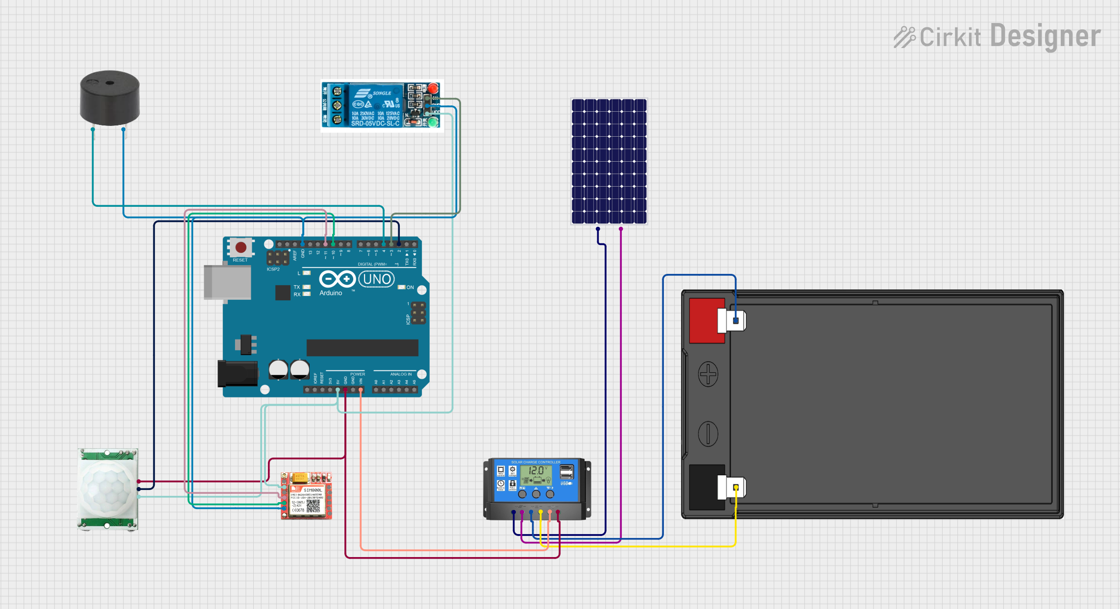
Circuit Documentation
Summary
This circuit is designed to detect motion using a PIR sensor and respond by activating a buzzer and a relay. Additionally, it sends an SMS alert using a SIM800L GSM module. The circuit is powered by a solar panel and a 12V 7Ah battery, managed by a solar charge controller. The Arduino UNO microcontroller is the central unit that processes the sensor input and controls the output devices.
Component List
Arduino UNO
- Description: Microcontroller board based on the ATmega328P.
- Pins: UNUSED, IOREF, Reset, 3.3V, 5V, GND, Vin, A0, A1, A2, A3, A4, A5, SCL, SDA, AREF, D13, D12, D11, D10, D9, D8, D7, D6, D5, D4, D3, D2, D1, D0
PIR/Motion Sensor
- Description: Passive Infrared Sensor for motion detection.
- Pins: GND, OUTPUT, VCC
5V Relay
- Description: Electromechanical relay for switching high power devices.
- Pins: Normally Open, Common terminal, Normally Closed, In, GND, VCC
SIM800L
- Description: GSM/GPRS module for sending SMS and data communication.
- Pins: NFT, RING, VCC, DTR, RST, MIC +, RXD, MIC-, TXD, SPK+, GND, SPK-
Buzzer
- Description: Simple piezoelectric buzzer for sound alerts.
- Pins: PIN, GND
Solar Panel
- Description: Solar panel for generating electrical power.
- Pins: +, -
12V 7Ah Battery
- Description: Rechargeable battery for storing electrical energy.
- Pins: 12v +, 12v -
Solar Charge Controller
- Description: Manages the charging of the battery from the solar panel.
- Pins: Solar Cell +, Solar Cell -, Battery +, Battery -, Load +, Load -
Wiring Details
Arduino UNO
5V connected to:
- 5V Relay (VCC)
- PIR/Motion Sensor (VCC)
- SIM800L (VCC)
GND connected to:
- PIR/Motion Sensor (GND)
- Solar Charge Controller (Load -)
- Buzzer (GND)
- 5V Relay (GND)
- SIM800L (GND)
Vin connected to:
- Solar Charge Controller (Load +)
D11 connected to:
- SIM800L (RXD)
D10 connected to:
- SIM800L (TXD)
D4 connected to:
- Buzzer (PIN)
D3 connected to:
- 5V Relay (In)
D2 connected to:
- PIR/Motion Sensor (OUTPUT)
PIR/Motion Sensor
GND connected to:
- Arduino UNO (GND)
OUTPUT connected to:
- Arduino UNO (D2)
VCC connected to:
- Arduino UNO (5V)
5V Relay
VCC connected to:
- Arduino UNO (5V)
GND connected to:
- Arduino UNO (GND)
In connected to:
- Arduino UNO (D3)
SIM800L
VCC connected to:
- Arduino UNO (5V)
GND connected to:
- Arduino UNO (GND)
RXD connected to:
- Arduino UNO (D11)
TXD connected to:
- Arduino UNO (D10)
Buzzer
PIN connected to:
- Arduino UNO (D4)
GND connected to:
- Arduino UNO (GND)
Solar Panel
+ connected to:
- Solar Charge Controller (Solar Cell +)
- connected to:
- Solar Charge Controller (Solar Cell -)
12V 7Ah Battery
12v + connected to:
- Solar Charge Controller (Battery +)
12v - connected to:
- Solar Charge Controller (Battery -)
Solar Charge Controller
Solar Cell + connected to:
- Solar Panel (+)
Solar Cell - connected to:
- Solar Panel (-)
Battery + connected to:
- 12V 7Ah Battery (12v +)
Battery - connected to:
- 12V 7Ah Battery (12v -)
Load + connected to:
- Arduino UNO (Vin)
Load - connected to:
- Arduino UNO (GND)
Documented Code
#include <SoftwareSerial.h>

SoftwareSerial gsmSerial(10, 11); // RX, TX for SIM800L
int pirSensor = 2; // PIR motion sensor pin
int buzzer = 4; // Buzzer pin
int relay = 3; // Relay pin

void setup() {
  pinMode(pirSensor, INPUT);
  pinMode(buzzer, OUTPUT);
  pinMode(relay, OUTPUT);

  Serial.begin(9600);
  gsmSerial.begin(9600);

  // Initialize GSM module
  delay(1000);
  gsmSerial.println("AT"); // Check if the module is working
  delay(1000);
  gsmSerial.println("AT+CMGF=1"); // Set SMS mode
  delay(1000);
}

void loop() {
  if (digitalRead(pirSensor) == HIGH) { // Motion detected
    digitalWrite(buzzer, HIGH); // Activate buzzer
    digitalWrite(relay, HIGH); // Activate relay (e.g., for alarm)

    // Send SMS alert
    sendSMS("Motion detected in the farm!");

    delay(10000); // Wait for 10 seconds before checking again
    digitalWrite(buzzer, LOW); // Deactivate buzzer
    digitalWrite(relay, LOW); // Deactivate relay
  }
  delay(100); // Short delay for stability
}

void sendSMS(String message) {
  gsmSerial.println("AT+CMGS=\"+91XXXXXXXXXX\""); // Replace with your phone number
  delay(1000);
  gsmSerial.println(message); // Message content
  delay(1000);
  gsmSerial.write(26); // Send Ctrl+Z to indicate end of message
  delay(1000);
}
This code initializes the GSM module, sets up the pins for the PIR sensor, buzzer, and relay, and continuously checks for motion. When motion is detected, it activates the buzzer and relay, and sends an SMS alert.