
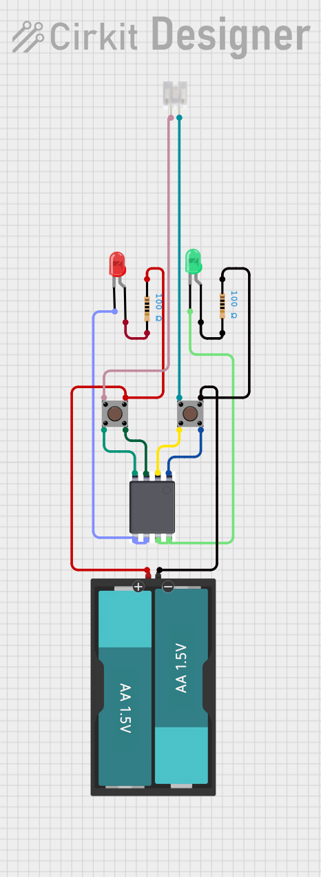
Circuit Documentation
Summary
This document provides a detailed overview of a simple electronic circuit. The circuit comprises various components including LEDs, resistors, pushbuttons, a battery, a motor driver IC (TA6568), and a connector. The circuit is designed to control the illumination of two LEDs (red and green) using pushbuttons and to manage power distribution through resistors and a battery. The TA6568 IC is used to interface the pushbuttons with the LEDs, potentially to control the brightness or toggle the state of the LEDs. The JST PH 2.0 connector is included for external connections. There is no embedded code provided for microcontrollers, indicating that the circuit functions purely on hardware logic.
Component List
LED: Two Pin (red)
- Description: A red LED with two pins, anode, and cathode.
LED: Two Pin (green)
- Description: A green LED with two pins, anode, and cathode.
TA6568
- Description: A motor driver IC with pins for bidirectional control (BI, FI, BO, FO), power (VCC), and ground (GND).
Pushbutton
- Description: A standard pushbutton with four pins, two for input and two for output.
Resistor
- Description: A resistor with a resistance value of 100 Ohms.
Battery AAx2 3V
- Description: A battery holder with two AA batteries providing a total of 3V.
JST PH 2.0 connector
- Description: A connector with two pins for making external connections.
Wiring Details
LED: Two Pin (red)
- Cathode connected to TA6568 FO pin.
- Anode connected to a 100 Ohm resistor.
LED: Two Pin (green)
- Cathode connected to TA6568 BO pin.
- Anode connected to a 100 Ohm resistor.
TA6568
- BI pin connected to Pushbutton Pin 4 (out).
- FI pin connected to Pushbutton Pin 2 (in).
- GND pin connected to Pushbutton Pin 4 (out).
- VCC pin connected to Pushbutton Pin 2 (in).
- FO pin connected to the cathode of the red LED.
- BO pin connected to the cathode of the green LED.
Pushbutton
- Pin 3 (out) connected to a 100 Ohm resistor and to the VCC of the battery.
- Pin 4 (out) connected to the BI and GND pins of TA6568.
- Pin 1 (in) connected to the JST PH 2.0 connector pin 2.
- Pin 2 (in) connected to the FI and VCC pins of TA6568.
Resistor
- One pin connected to the anode of an LED.
- The other pin connected to the corresponding pushbutton Pin 3 (out) or to the GND of the battery.
Battery AAx2 3V
- VCC connected to Pushbutton Pin 3 (out).
- GND connected to a 100 Ohm resistor and to Pushbutton Pin 3 (out).
JST PH 2.0 connector
- Pin 1 connected to Pushbutton Pin 1 (in).
- Pin 2 connected to Pushbutton Pin 1 (in).
Code Documentation
No code has been provided for this circuit as it operates purely on hardware logic without the need for a microcontroller or embedded software.