Arduino-Based Vehicle Tracking and Anti-Theft System
Circuit Documentation
Summary
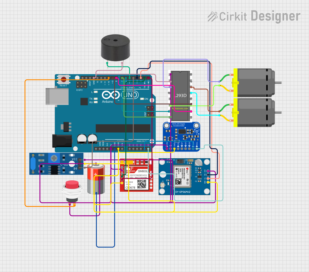
This circuit integrates various components to perform a set of functions that likely include communication, positioning, motion detection, and motor control. The central processing unit of the circuit is an Arduino UNO microcontroller, which interfaces with a SIM800L module for GSM communication, a Neo 6M GPS module for positioning, an Adafruit ADXL345 accelerometer for motion sensing, and a motor driver to control DC motors. Additional components include a vibration sensor, a push switch, a buzzer, and a 5V battery to power the circuit.
Component List
Sim800l
- GSM/GPRS module for cellular communication.
- Pins: NET, RST, VCC, RXD, TXD, GND.
Neo 6M GPS Module
- GPS receiver module for satellite positioning.
- Pins: GND, TX, RX, VCC.
Arduino UNO
- Microcontroller board based on the ATmega328P.
- Pins: UNUSED, IOREF, Reset, 3.3V, 5V, GND, Vin, A0-A5, SCL, SDA, AREF, D0-D13.
Adafruit ADXL345
- Accelerometer for measuring acceleration forces.
- Pins: VIN, 3.3V, GND, CS, INT1, INT2, SDO/ADDR, SDA/SDIO, SCL.
SW-420 Vibration Sensor
- Sensor for detecting vibrations.
- Pins: vcc, Ground, Digital output.
5v Battery
- Power source for the circuit.
- Pins: +, -.
Motor Driver
- Interface for controlling DC motors.
- Pins: pin 1-16.
DC Motor
- Electric motor powered by direct current.
- Pins: pin 1, pin 2.
2Pin Push Switch
- Simple push-button switch.
- Pins: Input +, Output +.
Buzzer
- Device for generating sound.
- Pins: PIN, GND.
Wiring Details
Sim800l
- VCC connected to 5V power net.
- RXD connected to Arduino UNO D1 (TX).
- TXD connected to Arduino UNO D0 (RX).
- GND connected to common ground net.
Neo 6M GPS Module
- VCC connected to 5V power net.
- TX connected to Arduino UNO D2.
- RX connected to Arduino UNO D3.
- GND connected to common ground net.
Arduino UNO
- 5V and GND pins provide power and ground to various components.
- A4 (SDA) and A5 (SCL) connected to Adafruit ADXL345 for I2C communication.
- D0-D10 used for interfacing with Sim800l, Neo 6M GPS Module, vibration sensor, buzzer, push switch, and motor driver.
Adafruit ADXL345
- VIN connected to 5V power net.
- GND connected to common ground net.
- SDA/SDIO connected to Arduino UNO A4.
- SCL connected to Arduino UNO A5.
SW-420 Vibration Sensor
- VCC connected to 5V power net.
- Ground connected to common ground net.
- Digital output connected to Arduino UNO D4.
5v Battery
- connected to 5V power net.
- connected to common ground net.
Motor Driver
- Pin 1 connected to 5V power net.
- Pin 2, pin 10, pin 11, and pin 8 connected to Arduino UNO D8, D9, D6, and D7 respectively for motor control signals.
- Pin 3 and pin 6 connected to DC Motor 1.
- Pin 13 and pin 14 connected to DC Motor 2.
DC Motor
- Two instances, each connected to the motor driver.
2Pin Push Switch
- Input + connected to 5V power net.
- Output + connected to Arduino UNO D10.
Buzzer
- PIN connected to Arduino UNO D5.
- GND connected to common ground net.
Documented Code
void setup() {
  // put your setup code here, to run once:

}

void loop() {
  // put your main code here, to run repeatedly:

}
The provided code is a template for the Arduino UNO microcontroller. The setup() function is called once when the microcontroller is powered on or reset. It is used to initialize variables, pin modes, start using libraries, etc. The loop() function is called repeatedly and contains the main logic of the program. The actual implementation details need to be filled in based on the specific requirements of the circuit's operation.