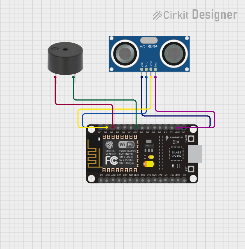
ESP8266 NodeMCU Controlled Ultrasonic Distance Detector with Buzzer Alert

Circuit Documentation
Summary
The circuit in question is designed to interface an ESP8266 NodeMCU microcontroller with an HC-SR04 Ultrasonic Sensor and a buzzer. The ESP8266 NodeMCU is responsible for controlling the sensor to measure distances and triggering the buzzer based on certain conditions. The HC-SR04 Ultrasonic Sensor is used for distance measurement, while the buzzer provides an audible alert. The circuit is powered by the 3.3V supply from the ESP8266 NodeMCU, and common ground connections are established between all components.
Component List
ESP8266 NodeMCU
- Description: A Wi-Fi capable microcontroller module based on the ESP8266 chip.
- Pins: D0, D1, D2, D3, D4, 3V3, GND, D5, D6, D7, D8, RX, TX, A0, RSV, SD3, SD2, SD1, CMD, SD0, CLK, EN, RST, VIN
HC-SR04 Ultrasonic Sensor
- Description: An ultrasonic distance sensor capable of measuring distances by emitting ultrasonic waves and measuring the time taken for the echo to return.
- Pins: VCC, TRIG, ECHO, GND
Buzzer
- Description: An electronic buzzer that produces sound when an electrical signal is applied.
- Pins: PIN, GND
Wiring Details
ESP8266 NodeMCU
- D0 connected to HC-SR04 TRIG pin
- D1 connected to HC-SR04 ECHO pin
- D2 connected to Buzzer PIN
- GND connected to Buzzer GND and HC-SR04 GND
- 3V3 connected to HC-SR04 VCC
HC-SR04 Ultrasonic Sensor
- TRIG connected to ESP8266 NodeMCU D0
- ECHO connected to ESP8266 NodeMCU D1
- VCC connected to ESP8266 NodeMCU 3V3
- GND connected to ESP8266 NodeMCU GND
Buzzer
- PIN connected to ESP8266 NodeMCU D2
- GND connected to ESP8266 NodeMCU GND
Documented Code
No code has been provided for the microcontroller. The documentation of the code would typically include a description of the functionality, setup, and main loop, along with comments explaining the purpose of each section of the code. Since no code is available, this section cannot be completed. If code becomes available, it should be added here with appropriate comments and explanations.