
Circuit Documentation
Summary
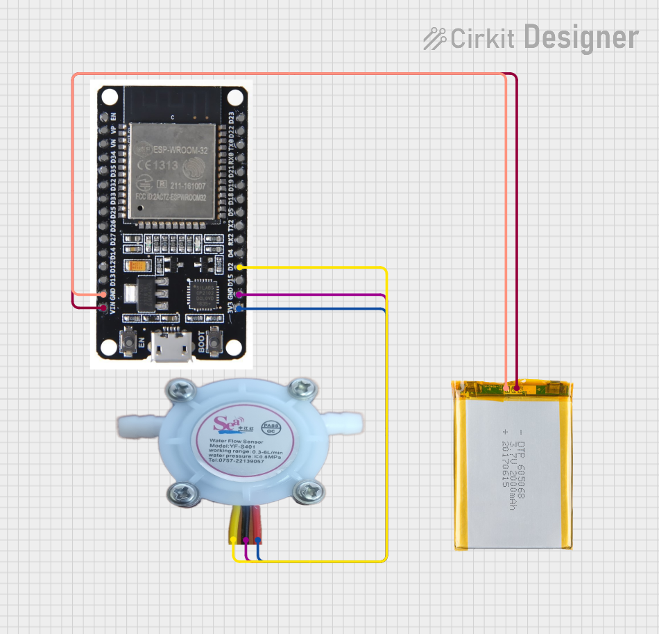
This circuit is designed to measure the water flow rate using a YF-S401 Water Flow Rate Sensor and an ESP32 microcontroller. The ESP32 is powered by a 2000mAh battery and connects to WiFi to allow users to view their water usage in real-time through a web server.
Component List
ESP32
- Description: A powerful microcontroller with built-in WiFi and Bluetooth capabilities.
- Pins: EN, VP, VN, D34, D35, D32, D33, D25, D26, D27, D14, D12, D13, GND, VIN, 3V3, D15, D2, D4, RX2, TX2, D5, D18, D19, D21, RX0, TX0, D22, D23, BOOT
Water Flow Rate Sensor YF-S401
- Description: A sensor used to measure the flow rate of water.
- Pins: GND negative, IN positive, OUT signal output
2000mAh Battery
- Description: A rechargeable battery used to power the ESP32.
- Pins: VCC, GND
Wiring Details
ESP32
- GND connected to GND of the 2000mAh Battery
- VIN connected to VCC of the 2000mAh Battery
- 3V3 connected to IN positive of the Water Flow Rate Sensor YF-S401
- GND connected to GND negative of the Water Flow Rate Sensor YF-S401
- D2 connected to OUT signal output of the Water Flow Rate Sensor YF-S401
Water Flow Rate Sensor YF-S401
- GND negative connected to GND of the ESP32
- IN positive connected to 3V3 of the ESP32
- OUT signal output connected to D2 of the ESP32
2000mAh Battery
- GND connected to GND of the ESP32
- VCC connected to VIN of the ESP32
Code Documentation
sketch.ino
/*
 * This Arduino Sketch is designed for an ESP32 microcontroller connected to a
 * Water Flow Rate Sensor YF-S401. The code calculates the volume of water
 * consumed in liters and allows the user to view their water usage when
 * connected to the ESP32's WiFi.
 */

#include <WiFi.h>

// WiFi credentials
const char* ssid = "your_SSID";
const char* password = "your_PASSWORD";

// Water Flow Sensor
const int flowSensorPin = 2; // D2 pin on ESP32
volatile int pulseCount = 0;
float flowRate = 0.0;
float volume = 0.0;
unsigned long oldTime = 0;

// Web server
WiFiServer server(80);

void IRAM_ATTR pulseCounter() {
  pulseCount++;
}

void setup() {
  Serial.begin(115200);
  pinMode(flowSensorPin, INPUT_PULLUP);
  attachInterrupt(digitalPinToInterrupt(flowSensorPin), pulseCounter, FALLING);

  // Connect to WiFi
  WiFi.begin(ssid, password);
  while (WiFi.status() != WL_CONNECTED) {
    delay(1000);
    Serial.println("Connecting to WiFi...");
  }
  Serial.println("Connected to WiFi");
  server.begin();
}

void loop() {
  if ((millis() - oldTime) > 1000) { // Only process once per second
    detachInterrupt(flowSensorPin);
    flowRate = ((1000.0 / (millis() - oldTime)) * pulseCount) / 7.5; // L/min
    oldTime = millis();
    volume += (flowRate / 60.0); // Convert to liters
    pulseCount = 0;
    attachInterrupt(digitalPinToInterrupt(flowSensorPin), pulseCounter, FALLING);
  }

  WiFiClient client = server.available();
  if (client) {
    Serial.println("New Client.");
    String currentLine = "";
    while (client.connected()) {
      if (client.available()) {
        char c = client.read();
        Serial.write(c);
        if (c == '\n') {
          if (currentLine.length() == 0) {
            client.println("HTTP/1.1 200 OK");
            client.println("Content-type:text/html");
            client.println();
            client.print("<html><body><h1>Water Usage</h1>");
            client.print("<p>Volume: ");
            client.print(volume);
            client.print(" L</p>");
            client.print("</body></html>");
            break;
          } else {
            currentLine = "";
          }
        } else if (c != '\r') {
          currentLine += c;
        }
      }
    }
    client.stop();
    Serial.println("Client Disconnected.");
  }
}
user.h
// This file is currently empty.
This documentation provides a comprehensive overview of the circuit, including the components used, their wiring details, and the code running on the ESP32 microcontroller.