
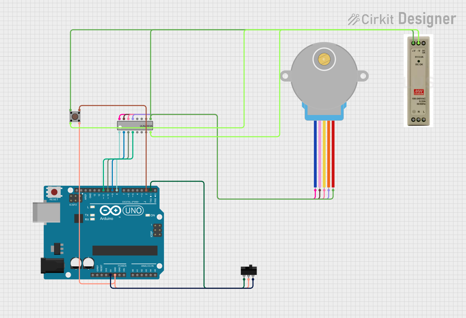
Circuit Documentation
Summary
This circuit is designed to control a 28BYJ-48 Stepper Motor using an Arduino UNO microcontroller and a ULN2003A driver. The motor's rotation direction can be changed with a toggle switch, and a pushbutton is used to initiate a control sequence. A 5V Power Supply Unit (PSU) provides power to the system.
Component List
Arduino UNO
- Microcontroller board based on the ATmega328P
- It has 14 digital input/output pins, 6 analog inputs, a 16 MHz quartz crystal, a USB connection, a power jack, an ICSP header, and a reset button.
Toggle Switch
- A simple switch that connects or disconnects an electrical circuit.
- It has three terminals: L1, COM, and L2.
28BYJ-48 Stepper Motor
- A small, 5V geared stepping motor with a 1/64 reduction gear ratio.
- It has five wires: BLUE, PINK, YELLOW, ORANGE, and RED.
ULN2003A
- A 7-channel Darlington array which is used to interface between low-level logic circuitry and multiple peripheral power loads.
- It has 16 pins including 7 inputs, 7 outputs, a common pin (COM), and a ground pin (GND).
5V PSU
- A power supply unit that provides a regulated 5V output.
- It has multiple pins for 5V output, ground, and AC input.
Pushbutton
- A momentary switch that completes a circuit when pressed.
- It has four pins: two for the input side (Pin 1 and Pin 2) and two for the output side (Pin 3 and Pin 4).
Wiring Details
Arduino UNO
- 5V: Connected to the Toggle Switch (L2)
- GND: Connected to the Pushbutton (Pin 4 out) and Toggle Switch (COM)
- D2: Connected to the Pushbutton (Pin 3 out)
- D8: Connected to ULN2003A (Input 1)
- D9: Connected to ULN2003A (Input 2)
- D10: Connected to ULN2003A (Input 3)
- D11: Connected to ULN2003A (Input 4)
Toggle Switch
- L1: Connected to Arduino UNO (D1)
- COM: Connected to Arduino UNO (GND)
- L2: Connected to Arduino UNO (5V)
28BYJ-48 Stepper Motor
- BLUE: Connected to ULN2003A (Output 1)
- PINK: Connected to ULN2003A (Output 2)
- YELLOW: Connected to ULN2003A (Output 3)
- ORANGE: Connected to ULN2003A (Output 4)
- RED: Connected to 5V PSU (5V+)
ULN2003A
- Input 1: Connected to Arduino UNO (D8)
- Input 2: Connected to Arduino UNO (D9)
- Input 3: Connected to Arduino UNO (D10)
- Input 4: Connected to Arduino UNO (D11)
- Output 1: Connected to 28BYJ-48 Stepper Motor (BLUE)
- Output 2: Connected to 28BYJ-48 Stepper Motor (PINK)
- Output 3: Connected to 28BYJ-48 Stepper Motor (YELLOW)
- Output 4: Connected to 28BYJ-48 Stepper Motor (ORANGE)
- COM: Connected to 5V PSU (5V+)
- GND: Connected to 5V PSU (GND)
5V PSU
- 5V+: Connected to ULN2003A (COM) and 28BYJ-48 Stepper Motor (RED)
- GND: Connected to ULN2003A (GND) and Pushbutton (Pin 2 in)
Pushbutton
- Pin 1 (in): Connected to 5V PSU (5V+)
- Pin 2 (in): Connected to 5V PSU (GND)
- Pin 3 (out): Connected to Arduino UNO (D2)
- Pin 4 (out): Connected to Arduino UNO (GND)
Documented Code
// Pin definitions
const int switchPin = 2; // Pin connected to the switch
const int motorPins[] = {8, 9, 10, 11}; // Pins connected to the ULN2003A inputs

// Variables
bool direction = true; // true for one direction, false for the other

void setup() {
  // Initialize motor pins as outputs
  for (int i = 0; i < 4; i++) {
    pinMode(motorPins[i], OUTPUT);
  }

  // Initialize switch pin as input
  pinMode(switchPin, INPUT_PULLUP); // Use internal pull-up resistor
}

void loop() {
  // Read the switch state
  int switchState = digitalRead(switchPin);

  // Determine the direction based on the switch state
  if (switchState == LOW) {
    direction = !direction; // Change direction if switch is closed
  }

  // Rotate the stepper motor
  if (direction) {
    stepMotorForward();
  } else {
    stepMotorBackward();
  }

  delay(100); // Adjust delay as needed
}

void stepMotorForward() {
  // Sequence for forward rotation
  digitalWrite(motorPins[0], HIGH);
  digitalWrite(motorPins[1], LOW);
  digitalWrite(motorPins[2], LOW);
  digitalWrite(motorPins[3], LOW);
  delay(10);

  digitalWrite(motorPins[0], LOW);
  digitalWrite(motorPins[1], HIGH);
  digitalWrite(motorPins[2], LOW);
  digitalWrite(motorPins[3], LOW);
  delay(10);

  digitalWrite(motorPins[0], LOW);
  digitalWrite(motorPins[1], LOW);
  digitalWrite(motorPins[2], HIGH);
  digitalWrite(motorPins[3], LOW);
  delay(10);

  digitalWrite(motorPins[0], LOW);
  digitalWrite(motorPins[1], LOW);
  digitalWrite(motorPins[2], LOW);
  digitalWrite(motorPins[3], HIGH);
  delay(10);
}

void stepMotorBackward() {
  // Sequence for backward rotation
  digitalWrite(motorPins[0], LOW);
  digitalWrite(motorPins[1], LOW);
  digitalWrite(motorPins[2], LOW);
  digitalWrite(motorPins[3], HIGH);
  delay(10);

  digitalWrite(motorPins[0], LOW);
  digitalWrite(motorPins[1], LOW);
  digitalWrite(motorPins[2], HIGH);
  digitalWrite(motorPins[3], LOW);
  delay(10);

  digitalWrite(motorPins[0], LOW);
  digitalWrite(motorPins[1], HIGH);
  digitalWrite(motorPins[2], LOW);
  digitalWrite(motorPins[3], LOW);
  delay(10);

  digitalWrite(motorPins[0], HIGH);
  digitalWrite(motorPins[1], LOW);
  digitalWrite(motorPins[2], LOW);
  digitalWrite(motorPins[3], LOW);
  delay(10);
}
This code is responsible for controlling the stepper motor's direction and steps. The switchPin is used to read the state of the toggle switch, which determines the direction of the motor's rotation. The motorPins array defines the connections to the ULN2003A driver inputs. The stepMotorForward and stepMotorBackward functions define the sequence of energizing the motor coils to rotate the motor in either direction. The loop function continuously checks the switch state and commands the motor to step accordingly.