
Arduino Nano Controlled RF Receiver with SD Logging and Audio Output
View and Edit Project In Cirkit Designer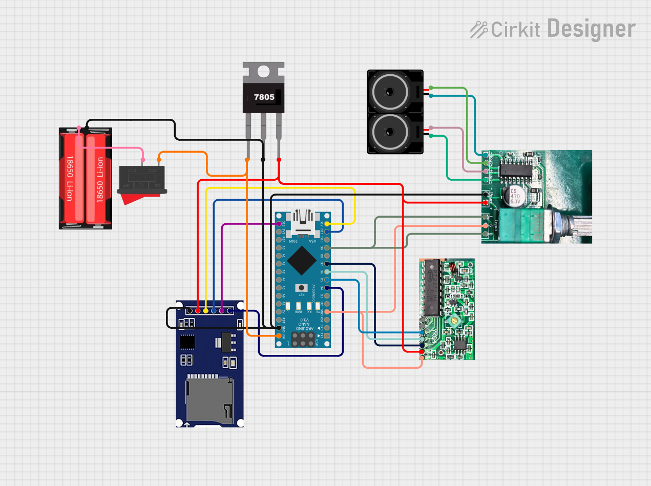
Circuit Documentation
Summary
This circuit integrates a variety of components to perform a specific function. It includes an Arduino Nano microcontroller, an RF 4Channel receiver operating at 433MHz, an SD card module for data storage, a PAM8403 audio amplifier with a regulator, two loudspeakers for audio output, a 7805 voltage regulator, an 18650 Li-Ion battery for power supply, and a rocker switch to control power flow. The Arduino Nano is programmed to interact with the RF receiver and the SD module, and it also controls the PAM8403 amplifier. The circuit is powered by the 18650 Li-Ion battery, regulated to 5V by the 7805 voltage regulator.
Component List
RF 4Channel Receiver 433Mhz
- Description: A radio frequency receiver that operates at 433MHz and has 4 digital output channels.
- Pins: D4, D3, D2, D1, D0, VCC, GND
Arduino Nano
- Description: A small, complete, and breadboard-friendly board based on the ATmega328 (Arduino Nano 3.x).
- Pins: D1/TX, D0/RX, RESET, GND, D2, D3, D4, D5, D6, D7, D8, D9, D10, D11/MOSI, D12/MISO, VIN, 5V, A7, A6, A5, A4, A3, A2, A1, A0, AREF, 3V3, D13/SCK
SD Module
- Description: A module that allows an Arduino board to read and write data to and from an SD card.
- Pins: CS, SCK, MOSI, MISO, VCC, GND
PAM8403 with Regulator
- Description: A small digital amplifier with an integrated voltage regulator.
- Pins: R-, R+, L+, L-, GND, VCC, L, G, B
Loudspeaker
- Description: An electroacoustic transducer that converts an electrical audio signal into a corresponding sound.
- Pins: pin1, pin2
7805 Voltage Regulator
- Description: A voltage regulator that outputs a regulated 5V from a higher voltage input.
- Pins: Vin, Gnd, Vout
18650 Li-Ion Battery
- Description: A rechargeable battery commonly used in laptops and other electronic devices.
- Pins: Positive, Negative
Rocker Switch
- Description: A switch that rocks back and forth to open or close the circuit.
- Pins: 1, 2
Wiring Details
RF 4Channel Receiver 433Mhz
- D2 connected to Arduino Nano D5
- D1 connected to Arduino Nano D6
- D0 connected to Arduino Nano D7
- VCC connected to 7805 Vout
- GND connected to common ground
Arduino Nano
- D5 connected to RF Receiver D2
- D6 connected to RF Receiver D1
- D7 connected to RF Receiver D0
- D4 connected to SD Module CS
- D11/MOSI connected to SD Module MOSI
- D12/MISO connected to SD Module MISO
- D13/SCK connected to SD Module SCK
- D9 connected to PAM8403 L and B
- GND connected to common ground
- VIN connected to Rocker Switch 1
SD Module
- CS connected to Arduino Nano D4
- SCK connected to Arduino Nano D13/SCK
- MOSI connected to Arduino Nano D11/MOSI
- MISO connected to Arduino Nano D12/MISO
- VCC connected to 7805 Vout
- GND connected to common ground
PAM8403 with Regulator
- R- connected to Loudspeaker pin1
- R+ connected to Loudspeaker pin2
- L+ connected to another Loudspeaker pin2
- L- connected to another Loudspeaker pin1
- GND connected to common ground
- VCC connected to 7805 Vout
- L and B connected to Arduino Nano D9
Loudspeaker
- pin1 connected to PAM8403 R- or L-
- pin2 connected to PAM8403 R+ or L+
7805 Voltage Regulator
- Vin connected to Rocker Switch 1
- Gnd connected to common ground
- Vout connected to VCC of RF Receiver, SD Module, and PAM8403
18650 Li-Ion Battery
- Positive connected to Rocker Switch 2
- Negative connected to common ground
Rocker Switch
- 1 connected to 7805 Vin and Arduino Nano VIN
- 2 connected to 18650 Li-Ion Positive
Documented Code
Arduino Nano Code (sketch.ino)
void setup() {
  // put your setup code here, to run once:

}

void loop() {
  // put your main code here, to run repeatedly:

}
Note: The provided code is a template and does not include specific functionality. It needs to be completed with the logic required for the circuit's intended operation.