
Arduino Mega 2560-Based Automated Inventory Management System with RFID and Load Sensing
View and Edit Project In Cirkit Designer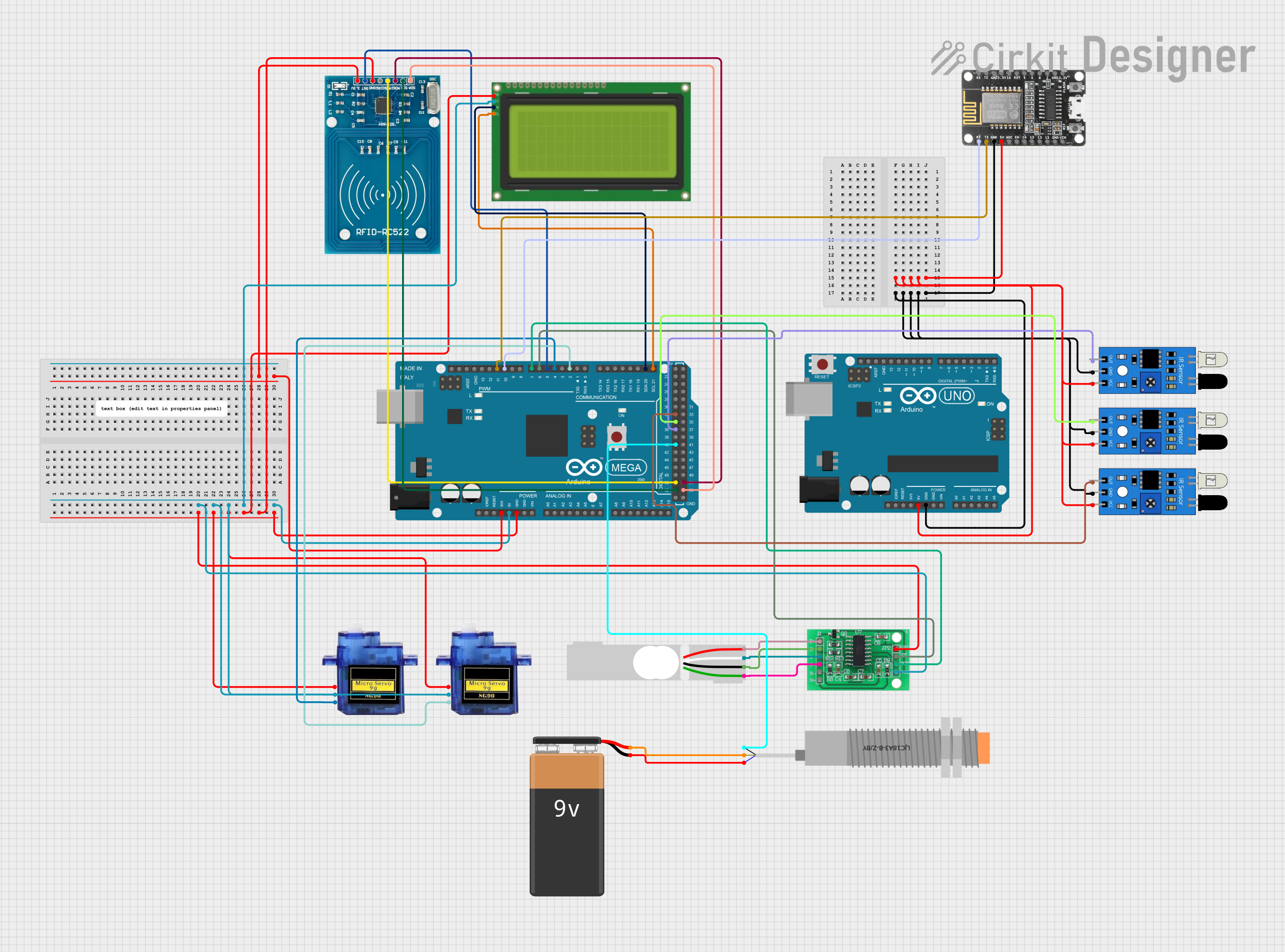
Circuit Documentation
Summary
The circuit in question is designed to interface various sensors and actuators with an Arduino Mega 2560 microcontroller. The circuit includes input devices such as RFID-RC522 for RFID reading, multiple IR sensors for object detection, a capacitive proximity sensor, and a load cell interfaced through an HX711 bridge sensor. Output devices include an LCD display with I2C interface and two micro servos. An ESP8285 ESP-M3 module is included for potential wireless communication. Power distribution is managed for both 5V and 3.3V components, and a 9V battery is included for power supply.
Component List
- Arduino Mega 2560: A microcontroller board based on the ATmega2560, with a variety of digital and analog I/O pins.
- RFID-RC522: An RFID reader/writer module.
- Lcd 20x4 i2c: A 20x4 character LCD display with an I2C interface.
- Micro servo 9G (x2): Small servos capable of precise position control.
- Load Cell - Red/white/black/green: A weight sensor for measuring force or load.
- HX711 - Bridge Sensor Interface: A precision 24-bit analog-to-digital converter (ADC) designed for weigh scales and industrial control applications to interface directly with a bridge sensor.
- IR Sensor (x3): Infrared sensors used for object detection.
- LJC18A3-B-Z/BY Capacitive Proximity Sensor: A sensor used to detect the presence of nearby objects without physical contact.
- Arduino UNO: A microcontroller board based on the ATmega328P, with a variety of digital and analog I/O pins.
- 9V Battery: A standard 9V battery used to power the circuit.
- ESP8285 ESP-M3: A compact Wi-Fi module that can be used for wireless communication.
Wiring Details
Arduino Mega 2560
- GND: Connected to the ground pins of the HX711, both Micro servos, the LCD, the RFID-RC522, and the ESP8285 ESP-M3.
- 5V: Powers the HX711, both Micro servos, and the LCD.
- 3V3: Powers the RFID-RC522.
- D21/SCL: Connected to the SCL pin of the LCD.
- D20/SDA: Connected to the SCA pin of the LCD.
- D2 PWM: Controls the PWM signal for one Micro servo.
- D4 PWM: Controls the PWM signal for the other Micro servo.
- D5 PWM: Connected to the RST pin of the RFID-RC522.
- D6 PWM: Connected to the DATA (OUT) pin of the HX711.
- D7 PWM: Connected to the SCK - CLOCK (IN) pin of the HX711.
- D10 PWM: Connected to the RX pin of the ESP8285 ESP-M3.
- D11 PWM: Connected to the TX pin of the ESP8285 ESP-M3.
- D52: Connected to the SCK pin of the RFID-RC522.
- D50: Connected to the MISO pin of the RFID-RC522.
- D40: Connected to the SIG (BLK) pin of the capacitive proximity sensor.
- D36: Connected to the out pin of one IR sensor.
- D34: Connected to the out pin of another IR sensor.
- D32: Connected to the out pin of the third IR sensor.
- D53: Connected to the SDA pin of the RFID-RC522.
- D51: Connected to the MOSI pin of the RFID-RC522.
RFID-RC522
- VCC (3.3V): Powered by the 3V3 pin of the Arduino Mega 2560.
Lcd 20x4 i2c
- GND: Ground connection.
- 5v: Powered by the 5V pin of the Arduino Mega 2560.
- SCA: Connected to the D20/SDA pin of the Arduino Mega 2560.
- SCL: Connected to the D21/SCL pin of the Arduino Mega 2560.
Micro servo 9G
- GND: Ground connection.
- +5V: Powered by the 5V pin of the Arduino Mega 2560.
- PWM: Receives PWM control signals from the D2 PWM and D4 PWM pins of the Arduino Mega 2560.
Load Cell - Red/white/black/green
- E+, A-, E-, A+: Connected to the corresponding pins on the HX711.
HX711 - Bridge Sensor Interface
- GND - GROUND: Ground connection.
- 3.3/3.5V Supply: Powered by the 5V pin of the Arduino Mega 2560.
- DATA (OUT): Connected to the D6 PWM pin of the Arduino Mega 2560.
- SCK - CLOCK (IN): Connected to the D7 PWM pin of the Arduino Mega 2560.
IR Sensor
- out: Connected to the D36, D34, and D32 pins of the Arduino Mega 2560.
- gnd: Ground connection.
- vcc: Powered by the 5V pin of the Arduino Mega 2560.
LJC18A3-B-Z/BY Capacitive Proximity Sensor
- VO (BLU): Connected to the negative terminal of the 9V Battery.
- VI (BRN): Connected to the positive terminal of the 9V Battery.
ESP8285 ESP-M3
- RX: Connected to the D10 PWM pin of the Arduino Mega 2560.
- TX: Connected to the D11 PWM pin of the Arduino Mega 2560.
- GND: Ground connection.
- 5V: Powered by the 5V pin of the Arduino Mega 2560.
Documented Code
Arduino Mega 2560 Code (sketch.ino)
void setup() {
  // put your setup code here, to run once:

}

void loop() {
  // put your main code here, to run repeatedly:

}
Arduino UNO Code (sketch.ino)
void setup() {
  // put your setup code here, to run once:

}

void loop() {
  // put your main code here, to run repeatedly:

}
Note: The provided code for both the Arduino Mega 2560 and the Arduino UNO is a template with empty setup and loop functions. Actual implementation code will be required to control the components as per the circuit design.