
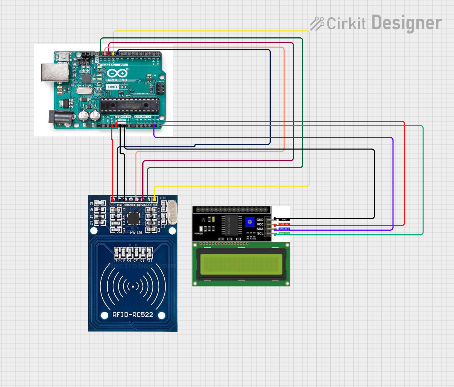
Circuit Documentation
Summary of the Circuit
This circuit integrates an RFID module with an Arduino UNO (deprecated) and an LCD I2C display. The RFID module is used for wireless communication and identification purposes, while the LCD display provides a user interface to display information. The Arduino UNO serves as the central processing unit, controlling the RFID module and the LCD display. The circuit is designed to operate on a 3.3V power supply for the RFID module and a 5V supply for the Arduino UNO and the LCD display.
Component List
RFID Module
- Pins: 3.3V, RST, GND, IRQ, MISO, MOSI, SCK, SDA
- Description: A module used for reading RFID tags.
- Purpose: To wirelessly read data from RFID tags and communicate with the Arduino UNO.
Arduino UNO (deprecated)
- Pins: IOREF, RESET, 3.3V, 5V, GND, Vin, A0 to A5, AREF, digital pins 0 to 13 (with some PWM capable pins denoted by '~')
- Description: A microcontroller board based on the ATmega328P.
- Purpose: To serve as the main controller for the circuit, interfacing with the RFID module and the LCD I2C display.
LCD I2C Display
- Pins: GND, VCC, SDA, SCL
- Description: A liquid crystal display that uses the I2C protocol for communication.
- Purpose: To display information to the user, receiving data from the Arduino UNO.
Wiring Details
RFID Module
- 3.3V: Connected to the 3.3V pin on the Arduino UNO.
- RST: Connected to digital pin 9 on the Arduino UNO.
- GND: Connected to the GND pin on the Arduino UNO.
- IRQ: Not connected in this circuit.
- MISO: Connected to digital pin 12 on the Arduino UNO.
- MOSI: Connected to digital pin 11 on the Arduino UNO.
- SCK: Connected to digital pin 13 on the Arduino UNO.
- SDA: Connected to digital pin 10 on the Arduino UNO.
Arduino UNO (deprecated)
- 3.3V: Provides power to the RFID module.
- 5V: Provides power to the LCD I2C Display.
- GND: Common ground for the circuit.
- Digital Pins 9, 10, 11, 12, 13: Interface with the RFID module.
- Analog Pins A4, A5: Interface with the LCD I2C Display using I2C communication.
LCD I2C Display
- VCC: Connected to the 5V pin on the Arduino UNO.
- GND: Connected to the GND pin on the Arduino UNO.
- SDA: Connected to analog pin A4 on the Arduino UNO.
- SCL: Connected to analog pin A5 on the Arduino UNO.
Documented Code
No code has been provided for the microcontrollers in the circuit. To fully utilize the circuit, embedded code for the Arduino UNO is required to handle communication with the RFID module and the LCD I2C display. The code should initialize the necessary libraries, set up the I2C communication, and implement the logic for reading RFID tags and displaying the information on the LCD.