
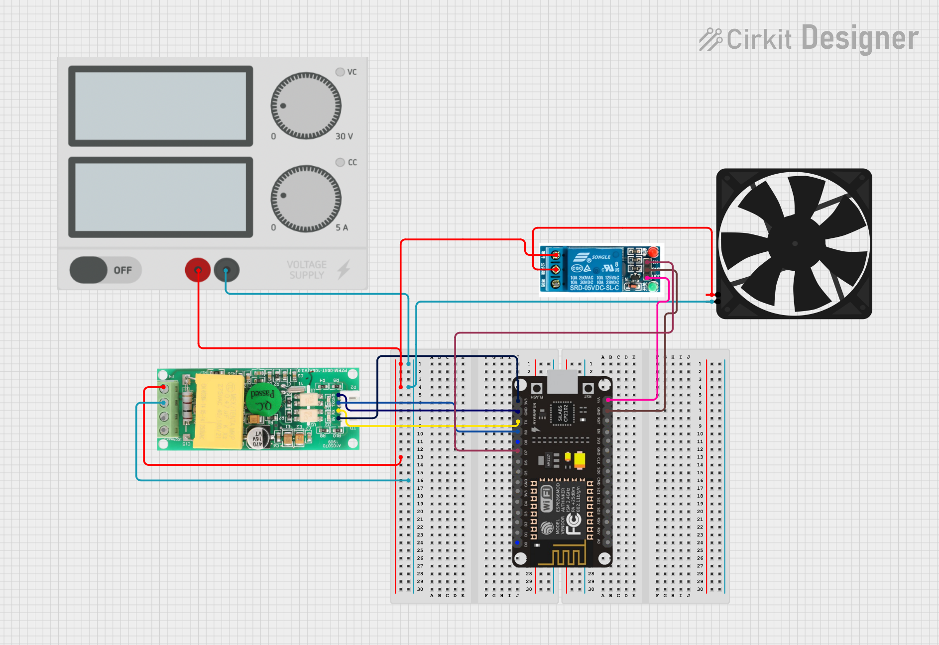
IoT Fan Project Documentation
Summary
This project involves an IoT-enabled fan control system using an ESP8266 NodeMCU microcontroller. The system controls a fan through a relay module and monitors power consumption using a PZEM004T power meter. The fan can be turned on or off via the relay, and power consumption data is read from the PZEM004T and can be sent to a server or displayed.
Component List
ESP8266 NodeMCU
- Description: A low-cost Wi-Fi microcontroller with GPIO, ADC, and UART capabilities.
- Pins: D0, D1, D2, D3, D4, 3V3, GND, D5, D6, D7, D8, RX, TX, A0, RSV, SD3, SD2, SD1, CMD, SD0, CLK, EN, RST, VIN
Fan
- Description: A simple DC fan.
- Pins: GND, 5V
PZEM004T
- Description: A power meter module for measuring voltage, current, power, and energy.
- Pins: VCC, RX, TX, GND, IN, OUT
Power Supply
- Description: Provides power to the circuit.
- Pins: +, -
5V Relay
- Description: A relay module for switching the fan on and off.
- Pins: Normally Open, Common terminal, Normally Closed, In, GND, VCC
Wiring Details
ESP8266 NodeMCU
- D7 connected to 5V Relay pin In
- RX connected to PZEM004T pin TX
- TX connected to PZEM004T pin RX
- GND connected to PZEM004T pin GND
- 3V3 connected to PZEM004T pin VCC
- GND connected to 5V Relay pin GND
- VIN connected to 5V Relay pin VCC
Fan
- GND connected to Power Supply pin -
- 5V connected to 5V Relay pin Common terminal
PZEM004T
- OUT connected to Power Supply pin +
- IN connected to Power Supply pin -
- TX connected to ESP8266 NodeMCU pin RX
- RX connected to ESP8266 NodeMCU pin TX
- GND connected to ESP8266 NodeMCU pin GND
- VCC connected to ESP8266 NodeMCU pin 3V3
Power Supply
- + connected to PZEM004T pin OUT
- - connected to Fan pin GND
- - connected to PZEM004T pin IN
5V Relay
- Normally Open connected to Power Supply pin +
- Common terminal connected to Fan pin 5V
- In connected to ESP8266 NodeMCU pin D7
- GND connected to ESP8266 NodeMCU pin GND
- VCC connected to ESP8266 NodeMCU pin VIN
Code Documentation
ESP8266 NodeMCU Code
/*
 * IoT Fan Project
 * This Arduino sketch is for an ESP8266 microcontroller. It controls a fan
 * through a relay module and monitors power consumption using a PZEM004T
 * power meter. The fan can be turned on or off via the relay, and power
 * consumption data is read from the PZEM004T and can be sent to a server
 * or displayed.
 */

#include <SoftwareSerial.h>

// Pin definitions
const int relayPin = D7; // Relay trigger pin
const int rxPin = RX;    // RX pin for PZEM004T
const int txPin = TX;    // TX pin for PZEM004T

// Create a SoftwareSerial object for PZEM004T communication
SoftwareSerial pzemSerial(rxPin, txPin);

void setup() {
  // Initialize serial communication
  Serial.begin(115200);
  pzemSerial.begin(9600);

  // Initialize relay pin
  pinMode(relayPin, OUTPUT);
  digitalWrite(relayPin, LOW); // Ensure the relay is off initially

  // Print a startup message
  Serial.println("IoT Fan Project Initialized");
}

void loop() {
  // Example: Turn the fan on for 5 seconds, then off for 5 seconds
  digitalWrite(relayPin, HIGH); // Turn the relay on (fan on)
  delay(5000);                  // Wait for 5 seconds
  digitalWrite(relayPin, LOW);  // Turn the relay off (fan off)
  delay(5000);                  // Wait for 5 seconds

  // Read power consumption data from PZEM004T
  if (pzemSerial.available()) {
    String pzemData = pzemSerial.readStringUntil('\n');
    Serial.println("Power Data: " + pzemData);
  }
}
Fan Code
void setup() {
  // put your setup code here, to run once:

}

void loop() {
  // put your main code here, to run repeatedly:

}
This documentation provides a comprehensive overview of the IoT Fan Project, including a summary, detailed component list, wiring details, and documented code.