
ESP32-Based Smart Air Purifier with Wi-Fi and Blynk Integration
View and Edit Project In Cirkit Designer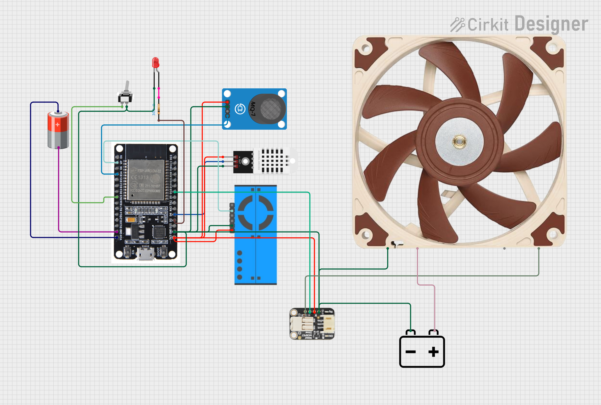
Smart Air Purifier Circuit Documentation
Summary
This document provides a detailed overview of a smart air purifier circuit. The circuit uses an ESP32 microcontroller to monitor indoor air quality, control a fan, and integrate with the Blynk app for real-time monitoring. The system includes various sensors and components to measure air quality, temperature, humidity, and control a fan based on the air quality index (AQI).
Component List
ESP32
- Description: Microcontroller with WiFi and Bluetooth capabilities.
- Pins: EN, VP, VN, D34, D35, D32, D33, D25, D26, D27, D14, D12, D13, GND, VIN, 3V3, D15, D2, D4, RX2, TX2, D5, D18, D19, D21, RX0, TX0, D22, D23, BOOT
DHT22
- Description: Temperature and humidity sensor.
- Pins: +, Out, -
MQ-7 Breakout
- Description: Carbon monoxide (CO) gas sensor.
- Pins: VCC, GND, DO, AO
12v PWM Fan (120mm)
- Description: Fan with PWM control for speed adjustment.
- Pins: GND, +12V, TACH, PWM
Adafruit MOSFET Driver
- Description: MOSFET driver for controlling high-power devices.
- Pins: GND, V+, In, Out
LED: Two Pin (red)
- Description: Red LED indicator.
- Pins: cathode, anode
12v Battery
- Description: 12V power source.
- Pins: -, +
5v Battery
- Description: 5V power source.
- Pins: +, -
Resistor
- Description: 300 Ohms resistor.
- Pins: pin1, pin2
PM2.5 Air Quality Sensor and Breadboard Adapter Kit - PMS5003
- Description: Particulate matter sensor for measuring PM2.5 levels.
- Pins: VCC, GND, SET, RX, TX, RST
Toggle Switch SPST
- Description: Single-pole single-throw toggle switch.
- Pins: L1, COM
Wiring Details
ESP32
- VP: Connected to TX of PM2.5 Air Quality Sensor
- D34: Connected to AO of MQ-7 Breakout
- D25: Connected to L1 of Toggle Switch
- GND: Connected to GND of 5v Battery, GND of PM2.5 Air Quality Sensor, GND of Adafruit MOSFET Driver, cathode of LED, GND of DHT22, GND of 12v PWM Fan, GND of MQ-7 Breakout
- VIN: Connected to + of 5v Battery
- 3V3: Connected to VCC of PM2.5 Air Quality Sensor, V+ of Adafruit MOSFET Driver, + of DHT22, VCC of MQ-7 Breakout
- D2: Connected to pin1 of Resistor
- D4: Connected to Out of DHT22
- D18: Connected to In of Adafruit MOSFET Driver
DHT22
- +: Connected to 3V3 of ESP32
- Out: Connected to D4 of ESP32
- -: Connected to GND of ESP32
MQ-7 Breakout
- VCC: Connected to 3V3 of ESP32
- GND: Connected to GND of ESP32
- AO: Connected to D34 of ESP32
12v PWM Fan (120mm)
- GND: Connected to GND of 12v Battery
- +12V: Connected to + of 12v Battery
- PWM: Connected to Out of Adafruit MOSFET Driver
Adafruit MOSFET Driver
- GND: Connected to GND of 12v Battery
- V+: Connected to 3V3 of ESP32
- In: Connected to D18 of ESP32
- Out: Connected to PWM of 12v PWM Fan
LED: Two Pin (red)
- cathode: Connected to GND of 12v Battery
- anode: Connected to pin2 of Resistor
12v Battery
- -: Connected to COM of Toggle Switch
- +: Connected to +12V of 12v PWM Fan
5v Battery
- +: Connected to VIN of ESP32
- -: Connected to GND of ESP32
Resistor
- pin1: Connected to D2 of ESP32
- pin2: Connected to anode of LED
PM2.5 Air Quality Sensor and Breadboard Adapter Kit - PMS5003
- VCC: Connected to 3V3 of ESP32
- GND: Connected to GND of 12v Battery
- TX: Connected to VP of ESP32
Toggle Switch SPST
- L1: Connected to D25 of ESP32
- COM: Connected to - of 12v Battery
Documented Code
// Smart Air Purifier Code with Blynk Integration in C
// This program uses an ESP32 microcontroller to monitor indoor air quality, adjust purification settings, and integrate with the Blynk app for real-time monitoring.

#include <WiFi.h>
#include <BlynkSimpleEsp32.h>
#include <DHT.h>

// Blynk Configuration
char auth[] = "Your_Blynk_Auth_Token";
char ssid[] = "YourWiFiSSID";
char pass[] = "YourWiFiPassword";

// Pins Configuration
#define DHT_PIN 4          // Pin for temperature and humidity sensor
#define PM_SENSOR_PIN 36   // Pin for particulate matter sensor (AQI)
#define FAN_PWM_PIN 18     // Pin for fan control
#define FILTER_LIFE_PIN 34 // Pin for filter life sensor
#define MODE_SWITCH_PIN 25 // Pin for manual mode switch
#define LED_INDICATOR_PIN 2

// Initialize Sensors and Components
DHT dht(DHT_PIN, DHT22);

// Variables
int fan_speed = 0;
int aqi = 0;
int filter_status = 0;

// Function Prototypes
void connectWifi();
void updateSensors();
void controlFan();

// Blynk Virtual Pin Handlers
BLYNK_WRITE(V0) {
  fan_speed = param.asInt();
  ledcWrite(0, fan_speed);
}

BLYNK_WRITE(V1) {
  digitalWrite(LED_INDICATOR_PIN, param.asInt());
}

void setup() {
  // Initialize Serial Monitor
  Serial.begin(115200);

  // Initialize Pins
  pinMode(FILTER_LIFE_PIN, INPUT);
  pinMode(MODE_SWITCH_PIN, INPUT);
  pinMode(LED_INDICATOR_PIN, OUTPUT);

  // Initialize DHT Sensor
  dht.begin();

  // Initialize PWM for Fan Control
  ledcSetup(0, 1000, 8); // Channel 0, 1kHz, 8-bit resolution
  ledcAttachPin(FAN_PWM_PIN, 0);

  // Connect to WiFi and Blynk
  connectWifi();
  Blynk.begin(auth, ssid, pass);
}

void loop() {
  Blynk.run();
  updateSensors();
  controlFan();
  delay(5000); // Wait 5 seconds between updates
}

void connectWifi() {
  WiFi.begin(ssid, pass);
  while (WiFi.status() != WL_CONNECTED) {
    delay(1000);
    Serial.println("Connecting to WiFi...");
  }
  Serial.println("Connected to WiFi");
}

void updateSensors() {
  // Read DHT Sensor
  float temperature = dht.readTemperature();
  float humidity = dht.readHumidity();

  // Read PM Sensor and Filter Life Sensor
  aqi = analogRead(PM_SENSOR_PIN);
  filter_status = analogRead(FILTER_LIFE_PIN);

  // Send data to Blynk
  Blynk.virtualWrite(V2, temperature);
  Blynk.virtualWrite(V3, humidity);
  Blynk.virtualWrite(V4, aqi);
  Blynk.virtualWrite(V5, filter_status);

  // Notify if filter needs replacement
  if (filter_status < 500) {
    Blynk.notify("Filter replacement required!");
  }

  // Debug Output
  Serial.print("Temperature: ");
  Serial.print(temperature);
  Serial.print(" C, Humidity: ");
  Serial.print(humidity);
  Serial.print(" %, AQI: ");
  Serial.print(aqi);
  Serial.print(", Filter Status: ");
  Serial.println(filter_status);
}

void controlFan() {
  // Adjust fan speed based on AQI
  if (aqi < 50) {
    fan_speed = 64; // Low speed
  } else if (aqi < 100) {
    fan