
Battery-Powered Piezo Sensor Array with LED Indicators and TP4056 Charging Module
View and Edit Project In Cirkit Designer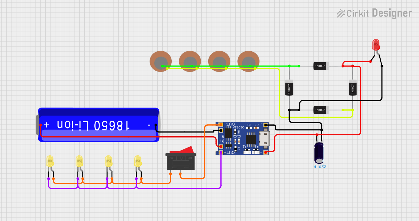
Circuit Documentation
Summary
This circuit is designed to utilize a 18650 Li-ion battery to power a TP4056 battery charging module, which in turn powers a series of LEDs and piezo sensors. The circuit includes rectifier diodes for protection and an electrolytic capacitor for smoothing the voltage. A rocker switch is used to control the power to the LEDs.
Component List
18650 Li-ion Battery
- Pins: +, -
- Description: A rechargeable lithium-ion battery.
- Purpose: Provides power to the circuit.
Piezo Sensor
- Pins: +, -
- Description: A sensor that generates a voltage when mechanical stress is applied.
- Purpose: Used to detect mechanical vibrations or impacts.
1N4007 Rectifier Diode
- Pins: Cathode, Anode
- Description: A diode used for rectification.
- Purpose: Protects the circuit by allowing current to flow in one direction only.
Electrolytic Capacitor
- Pins: +, -
- Description: A capacitor with a capacitance of 220 Farads.
- Purpose: Smooths out voltage fluctuations.
TP4056
- Pins: OUT-, B-, B+, OUT+, IN-, IN+
- Description: A lithium battery charging module.
- Purpose: Manages the charging of the 18650 Li-ion battery.
LED: Two Pin (red)
- Pins: cathode, anode
- Description: A red light-emitting diode.
- Purpose: Indicates the status of the circuit.
LED: Two Pin (yellow)
- Pins: cathode, anode
- Description: A yellow light-emitting diode.
- Purpose: Indicates the status of the circuit.
Rocker Switch
- Pins: 1, 2
- Description: A switch used to control the power.
- Purpose: Turns the LEDs on and off.
Wiring Details
18650 Li-ion Battery
- + Pin:
- Connected to B+ pin of TP4056.
- - Pin:
- Connected to B- pin of TP4056.
Piezo Sensor
- + Pin:
- Connected to Anode pin of 1N4007 Rectifier Diode.
- - Pin:
- Connected to Cathode pin of 1N4007 Rectifier Diode.
1N4007 Rectifier Diode
- Cathode Pin:
- Connected to IN+ pin of TP4056.
- Connected to Cathode pin of another 1N4007 Rectifier Diode.
- Connected to + pin of Electrolytic Capacitor.
- Connected to cathode pin of LED (red).
- Anode Pin:
- Connected to IN- pin of TP4056.
- Connected to - pin of Electrolytic Capacitor.
- Connected to Anode pin of another 1N4007 Rectifier Diode.
Electrolytic Capacitor
- + Pin:
- Connected to Cathode pin of 1N4007 Rectifier Diode.
- - Pin:
- Connected to IN- pin of TP4056.
TP4056
- OUT- Pin:
- Connected to pin 2 of Rocker Switch.
- B- Pin:
- Connected to - pin of 18650 Li-ion Battery.
- B+ Pin:
- Connected to + pin of 18650 Li-ion Battery.
- OUT+ Pin:
- Connected to cathode pin of LED (yellow).
LED: Two Pin (red)
- cathode Pin:
- Connected to Cathode pin of 1N4007 Rectifier Diode.
- anode Pin:
- Connected to IN- pin of TP4056.
LED: Two Pin (yellow)
- cathode Pin:
- Connected to OUT+ pin of TP4056.
- anode Pin:
- Connected to pin 1 of Rocker Switch.
Rocker Switch
- Pin 1:
- Connected to anode pin of LED (yellow).
- Pin 2:
- Connected to OUT- pin of TP4056.
Code
No microcontroller code is provided for this circuit.
This documentation provides a comprehensive overview of the circuit, including a detailed list of components and their wiring connections.