Cirkit Designer
Your all-in-one circuit design IDE
Home /
Project Documentation
Arduino UNO RFID-Activated AC Light Control
Circuit Documentation
Summary
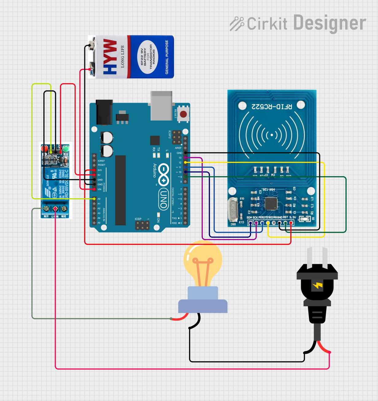
This circuit integrates an Arduino UNO microcontroller with an RFID-RC522 module, a 5V relay, an LED bulb designed for AC voltage, and an AC power source. The circuit is powered by a 9V battery. The Arduino UNO controls the RFID reader and the relay, which in turn controls the power to the LED bulb. The RFID-RC522 module is used for wireless communication and identification. The relay acts as an electrically operated switch that allows the Arduino to control the LED bulb with the AC power source.
Component List
Arduino UNO
- Microcontroller board based on the ATmega328P
- It has 14 digital input/output pins, 6 analog inputs, a 16 MHz quartz crystal, a USB connection, a power jack, an ICSP header, and a reset button.
RFID-RC522
- A radio frequency identification (RFID) module that operates at 13.56 MHz
- It is commonly used for contactless communication and can read and write to various RFID tags.
5V Relay
- An electromechanical switch that allows a low-power circuit to switch a relatively high current or voltage on and off.
- It has a coil that, when energized, creates a magnetic field that activates a switch.
LED Bulb AC / Bombillo AC
- An LED light bulb designed for alternating current (AC) power sources.
- It is used for illumination and can be controlled via the relay.
AC Source
- Provides alternating current (AC) power to the circuit.
- It is the main power source for the LED bulb.
9V Battery
- A standard 9-volt battery used to power the Arduino UNO and the RFID-RC522 module.
Wiring Details
Arduino UNO
3.3Vconnected to RFID-RC522 VCC (3.3V)5Vconnected to 5V relay VCCGNDconnected to 5V relay GND, RFID-RC522 GND, and 9V battery (-)Vinconnected to 9V battery (+)A0connected to 5V relay InD13connected to RFID-RC522 SCKD12connected to RFID-RC522 MISOD11connected to RFID-RC522 MOSID10connected to RFID-RC522 SDAD9connected to RFID-RC522 RST
RFID-RC522
VCC (3.3V)connected to Arduino UNO 3.3VRSTconnected to Arduino UNO D9GNDconnected to Arduino UNO GNDSCKconnected to Arduino UNO D13MISOconnected to Arduino UNO D12MOSIconnected to Arduino UNO D11SDAconnected to Arduino UNO D10
5V Relay
VCCconnected to Arduino UNO 5VGNDconnected to Arduino UNO GNDInconnected to Arduino UNO A0Normally Openconnected to LED bulb AC / Bombillo AC (+)Common terminalconnected to AC source (-)
LED Bulb AC / Bombillo AC
+connected to 5V relay Normally Open-connected to AC source (+)
AC Source
+connected to LED bulb AC / Bombillo AC (-)-connected to 5V relay Common terminal
9V Battery
+connected to Arduino UNO Vin-connected to Arduino UNO GND
Documented Code
Arduino UNO Code (sketch.ino)
void setup() {
  // put your setup code here, to run once:

}

void loop() {
  // put your main code here, to run repeatedly:

}
Note: The provided code is a template and does not contain any functional code to operate the circuit. The user must add the necessary code to initialize the RFID-RC522 module, read RFID tags, and control the relay to power the LED bulb.