
ESP32-Based Smart Environmental Monitoring System with Relay Control
View and Edit Project In Cirkit Designer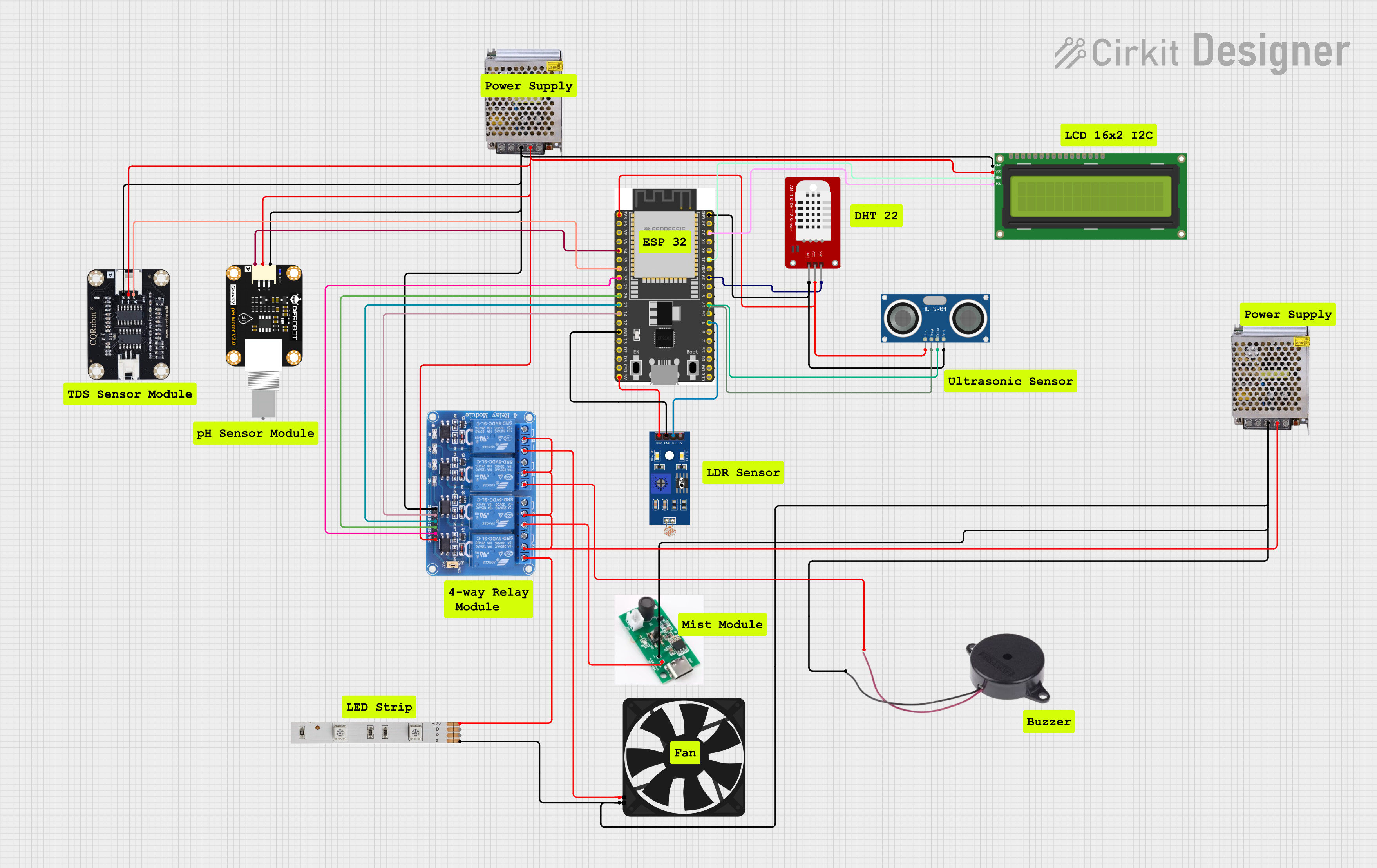
Circuit Documentation
Summary
The circuit in question appears to be a sensor and control system, likely for environmental monitoring and automation. It includes an ESP32 microcontroller for processing and connectivity, various sensors (DHT22 for temperature and humidity, PH sensor, TDS sensor for water quality, LDR for light detection, and an ultrasonic sensor), actuators (relays, fan, mist module, LED strip, buzzer), a display (I2C LCD), and power supply components.
Component List
ESP 32 Wroom Dev Kit
- Microcontroller development board based on the ESP32 chip.
- Provides WiFi and Bluetooth connectivity.
- Features a variety of GPIO pins for interfacing with sensors and actuators.
DHT22
- Digital temperature and humidity sensor.
- Provides high accuracy and long-term stability.
POWER SUPPLY 5V 5AMP
- Converts 220V AC to 5V DC output.
- Capable of supplying up to 5A of current.
Modulo Sensor PH
- Sensor module for measuring the pH level of a solution.
- Outputs an analog signal corresponding to the pH level.
TDS Sensor Board
- Sensor for measuring the Total Dissolved Solids in water.
- Outputs an analog signal that can be correlated to TDS levels.
LDR (Light Dependent Resistor)
- A sensor that changes resistance based on light intensity.
- Can be used to detect light levels in the environment.
HC-SR04 Ultrasonic Sensor
- Measures distance by emitting ultrasonic waves and timing their return.
- Used for non-contact distance measurement.
Relay 4 Channel 5v
- A module with 4 relays that can control high power devices.
- Each relay has Normally Open (NO) and Normally Closed (NC) connections.
Fan
- A simple 5V fan for cooling or air circulation.
LED Strip
- A strip of LEDs that can be used for lighting or signaling.
- Requires a 12V power supply.
Buzzer
- An audible signaling device.
- Can be used for alerts or notifications.
I2C LCD 16x2 Screen
- An alphanumeric display with 2 lines of 16 characters.
- Uses the I2C communication protocol.
Mist Module
- A device that produces mist, likely for humidification or cooling.
Wiring Details
ESP 32 Wroom Dev Kit
3V3connected to the VCC of DHT22 and HC-SR04 Ultrasonic Sensor.GPIO 34connected to the PH sensor module's analog output.GPIO 32connected to the TDS sensor board's analog output.GPIO 33,GPIO 26,GPIO 27,GPIO 14connected to Relay 4 Channel 5v inputs IN4, IN3, IN2, IN1 respectively.GNDconnected to the ground of LDR, HC-SR04 Ultrasonic Sensor, DHT22, and common ground net.V5connected to the VCC of LDR.GPIO 22andGPIO 21connected to the SCL and SDA pins of the I2C LCD 16x2 Screen.GPIO 19connected to the DAT pin of DHT22.GPIO 17andGPIO 16connected to the ECHO and TRIG pins of HC-SR04 Ultrasonic Sensor.GPIO 4connected to the D0 pin of LDR.
DHT22
GNDandVCCconnected to common ground and 3V3 from ESP32 respectively.DATconnected to GPIO 19 of ESP32.
POWER SUPPLY 5V 5AMP
GNDandGND (DC)connected to the common ground net.GND (DC)also connected to the VCC of Relay 4 Channel 5v, Modulo Sensor PH, TDS Sensor Board, and I2C LCD 16x2 Screen.
Modulo Sensor PH
Aconnected to GPIO 34 of ESP32.-connected to common ground net.+connected to VCC net.
TDS Sensor Board
Aconnected to GPIO 32 of ESP32.GNDandVCCconnected to common ground and VCC nets respectively.
LDR
A0andD0not connected in the provided net list.GNDandVCCconnected to common ground and V5 from ESP32 respectively.
HC-SR04 Ultrasonic Sensor
VCCconnected to 3V3 from ESP32.TRIGandECHOconnected to GPIO 16 and GPIO 17 of ESP32 respectively.GNDconnected to common ground net.
Relay 4 Channel 5v
GNDandVCCconnected to common ground and VCC nets respectively.IN1,IN2,IN3,IN4connected to GPIO 14, GPIO 27, GPIO 26, GPIO 33 of ESP32 respectively.COM1,COM2,COM3,COM4connected to common ground net.NO1,NO2,NO3,NO4connected to Fan, Buzzer, Mist Module, and LED Strip respectively.
Fan
5Vconnected to NO1 of Relay 4 Channel 5v.GNDconnected to common ground net.
LED Strip
+12Vconnected to NO4 of Relay 4 Channel 5v.Gconnected to common ground net.
Buzzer
POSITIVEconnected to NO2 of Relay 4 Channel 5v.NEGATIVEconnected to common ground net.
I2C LCD 16x2 Screen
SCLandSDAconnected to GPIO 22 and GPIO 21 of ESP32 respectively.VCC (5V)connected to VCC net.GNDconnected to common ground net.
Mist Module
Positiveconnected to NO3 of Relay 4 Channel 5v.Negativeconnected to common ground net.
Documented Code
No code was provided in the input. For a complete documentation, the embedded code running on the ESP32 microcontroller should be included. This code would typically initialize the GPIO pins, set up communication protocols (such as I2C for the LCD), read sensor data, control the relay states based on sensor inputs or external commands, and handle any wireless communication for remote monitoring or control.