Arduino UNO Controlled Traffic Light System with IR Sensors and I2C LCD Display
Circuit Documentation
Summary of the Circuit
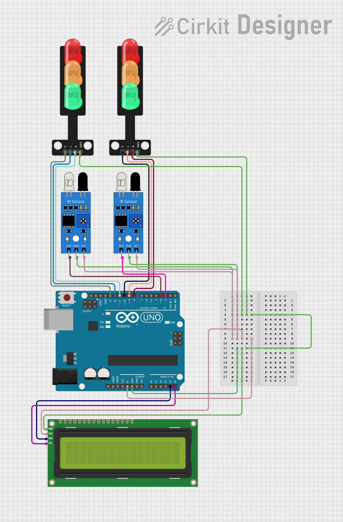
This circuit is designed to interface an Arduino UNO with multiple peripherals including two IR sensors, two traffic lights, and an I2C LCD 16x2 screen. The Arduino UNO acts as the central controller, managing inputs from the IR sensors and controlling the state of the traffic lights and displaying information on the LCD screen. The IR sensors are used to detect objects or motion, and their outputs are connected to the digital pins of the Arduino. The traffic lights are controlled by separate digital pins on the Arduino, allowing for individual control of each light. The I2C LCD screen is connected to the Arduino's I2C pins (A4 and A5) for data display.
Component List
Arduino UNO
- Description: A microcontroller board based on the ATmega328P.
- Purpose: Acts as the central processing unit of the circuit, reading sensor inputs and controlling the traffic lights and LCD screen.
IR Sensor (2x)
- Description: An infrared sensor capable of detecting objects or motion.
- Purpose: Provides input to the Arduino to trigger changes in the traffic light states.
Traffic Light (2x)
- Description: A module with three LEDs (Red, Yellow, Green) representing a traffic light.
- Purpose: Displays the current state of the traffic light as controlled by the Arduino.
I2C LCD 16x2 Screen
- Description: A 16x2 character LCD display that uses the I2C communication protocol.
- Purpose: Displays information or status messages as directed by the Arduino.
Wiring Details
Arduino UNO
- 5V: Connected to the VCC of both IR sensors and the VCC (5V) of the I2C LCD screen.
- GND: Connected to the GND of both IR sensors, both traffic lights, and the GND of the I2C LCD screen.
- A4 (SDA): Connected to the SDA pin of the I2C LCD screen.
- A5 (SCL): Connected to the SCL pin of the I2C LCD screen.
- D2: Connected to the output of one IR sensor.
- D3: Connected to the output of the other IR sensor.
- D8: Connected to the Red LED of one traffic light.
- D9: Connected to the Yellow LED of one traffic light.
- D10: Connected to the Green LED of one traffic light.
- D11: Connected to the Red LED of the other traffic light.
- D12: Connected to the Yellow LED of the other traffic light.
- D13: Connected to the Green LED of the other traffic light.
IR Sensor
- out: Connected to the D2 or D3 pin on the Arduino UNO.
- gnd: Connected to the GND pin on the Arduino UNO.
- vcc: Connected to the 5V pin on the Arduino UNO.
Traffic Light
- Green: Connected to the D10 or D13 pin on the Arduino UNO.
- Yellow: Connected to the D9 or D12 pin on the Arduino UNO.
- Red: Connected to the D8 or D11 pin on the Arduino UNO.
- GND: Connected to the GND pin on the Arduino UNO.
I2C LCD 16x2 Screen
- SCL: Connected to the A5 pin on the Arduino UNO.
- SDA: Connected to the A4 pin on the Arduino UNO.
- VCC (5V): Connected to the 5V pin on the Arduino UNO.
- GND: Connected to the GND pin on the Arduino UNO.
Documented Code
void setup() {
  // put your setup code here, to run once:

}

void loop() {
  // put your main code here, to run repeatedly:

}
The provided code is a template with empty setup() and loop() functions. The setup() function is intended for initialization code that runs once when the Arduino is powered on or reset. The loop() function contains the main logic of the program, which runs repeatedly as long as the Arduino is powered.
Further implementation is required to handle inputs from the IR sensors, control the traffic lights, and update the display on the I2C LCD screen.