
Arduino Mega 2560-Controlled Robotic Actuators with Joystick and Pushbutton Interface
View and Edit Project In Cirkit Designer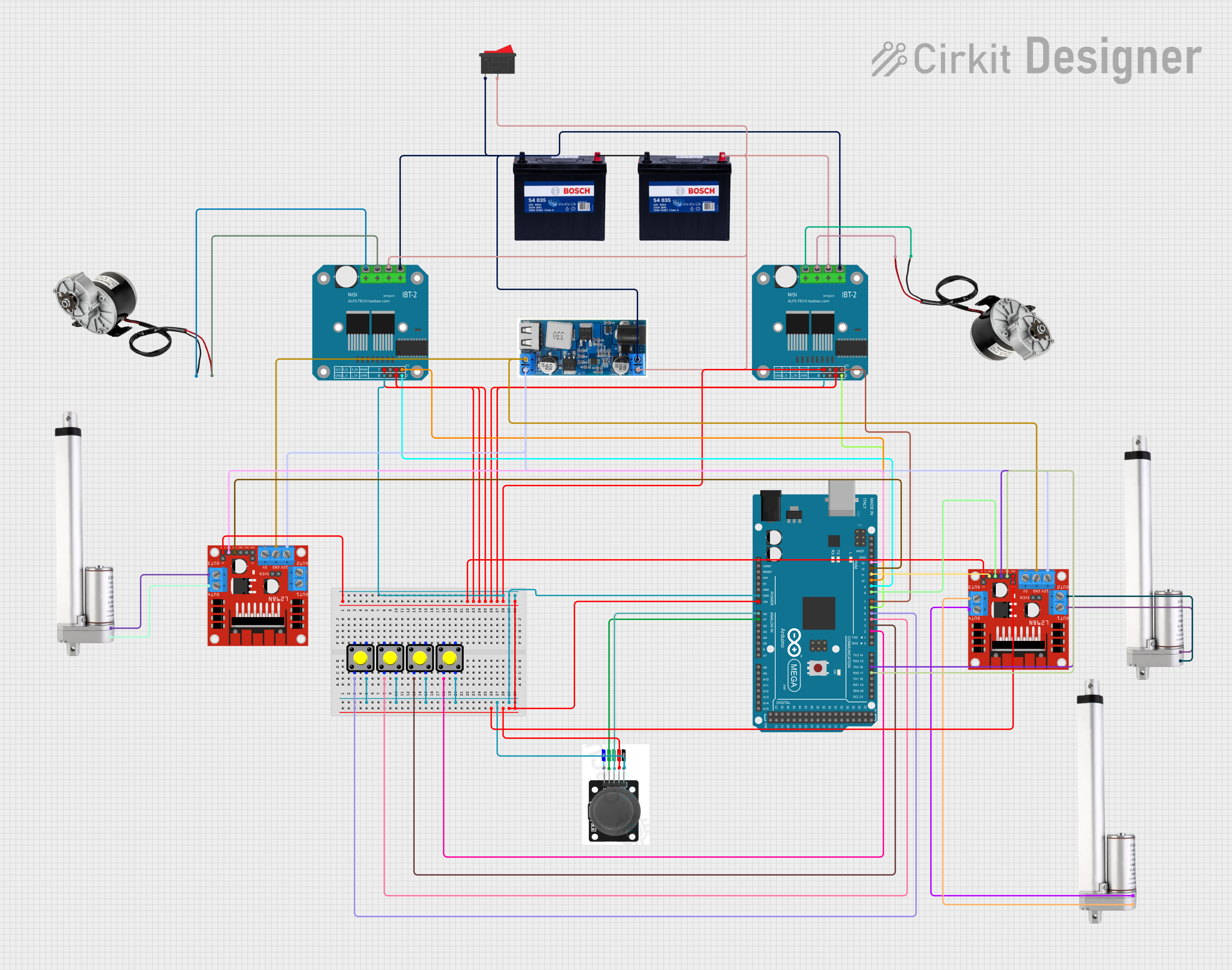
Circuit Documentation
Summary
This document provides a detailed overview of a circuit designed to control multiple DC motors and actuators using an Arduino Mega 2560 as the central microcontroller. The circuit includes motor drivers for handling high-current loads, pushbuttons for input, a joystick module for control, and power regulation components to manage the power supply.
Component List
Motors
- 250W 12V Electric Motor (Brushed DC)
- Description: A high-power motor for driving heavy loads.
- Actuator Motor
- Description: A motor used for linear actuation tasks.
Motor Drivers
- L298N DC Motor Driver
- Description: A dual H-bridge motor driver capable of driving a pair of DC motors or actuators.
- BTS7960 Motor Driver
- Description: A high-power motor driver designed for large current applications.
Power Supply
- 12V 200Ah Battery
- Description: A high-capacity battery providing the main power source for the circuit.
- 24/12V Buck Converter
- Description: A step-down voltage regulator to provide stable power to certain components.
Control Inputs
- Pushbutton
- Description: A simple pushbutton used for triggering actions.
- Joystick Module
- Description: A two-axis analog joystick with a built-in pushbutton for versatile control inputs.
- Rocker Switch
- Description: A switch used to control the power flow within the circuit.
Microcontroller
- Arduino Mega 2560
- Description: A microcontroller board based on the ATmega2560, with numerous digital and analog I/O pins.
Wiring Details
250W 12V Electric Motor (Brushed DC)
- POSITIF: Connected to the positive output of the corresponding BTS7960 Motor Driver.
- NEGATIF: Connected to the negative output of the corresponding BTS7960 Motor Driver.
Actuator Motor
- 12 V: Connected to the output of the corresponding L298N Motor Driver.
- Ground: Connected to the output of the corresponding L298N Motor Driver.
L298N DC Motor Driver
- OUT1, OUT2, OUT3, OUT4: Connected to the Actuator Motors.
- 12V: Connected to the 24/12V Buck Converter.
- GND: Connected to the ground rail.
- ENA, ENB: Connected to each other and to the enable pins of the BTS7960 Motor Drivers.
- IN1, IN2, IN3, IN4: Controlled by the Arduino Mega 2560.
BTS7960 Motor Driver
- Pin 1: Connected to the ground rail.
- Pin 3, Pin 5, Pin 7: Connected to the enable pins of the L298N Motor Drivers.
- Pin 4, Pin 8: Controlled by the Arduino Mega 2560.
- Pin 9: Connected to the ground of the 12V 200Ah Battery through a Rocker Switch.
- Pin 10: Connected to the positive terminal of the 12V 200Ah Battery through a Rocker Switch.
- Pin 11, Pin 12: Connected to the 250W 12V Electric Motors.
12V 200Ah Battery
- GND: Connected to the ground rail and the ground terminal of the BTS7960 Motor Drivers.
- 12V: Connected to the positive terminal of the BTS7960 Motor Drivers.
Pushbutton
- Pin 2: Connected to the digital I/O pins of the Arduino Mega 2560.
- Pin 3: Connected to the ground rail.
Joystick Module
- SW: Not connected in the provided net list.
- VRY, VRX: Connected to the analog inputs of the Arduino Mega 2560.
- VCC: Connected to the VIN of the Arduino Mega 2560.
- GND: Connected to the ground rail.
Arduino Mega 2560
- Digital I/O Pins (D2 PWM, D3 PWM, D4 PWM, D5 PWM, D6 PWM, D7 PWM, D8 PWM, D9 PWM, D10 PWM, D11 PWM, D12 PWM, D13 PWM): Connected to the control pins of the motor drivers and pushbuttons.
- Analog Input Pins (A0, A1): Connected to the joystick module.
- GND: Connected to the ground rail.
- VIN: Connected to the VCC of the joystick module.
Rocker Switch
- Pin 1: Connected to the ground of the 12V 200Ah Battery.
- Pin 2: Connected to the positive terminal of the 12V 200Ah Battery.
24/12V Buck Converter
- VIN+: Connected to the positive terminal of the 12V 200Ah Battery.
- VIN-: Connected to the ground of the 12V 200Ah Battery.
- 5V: Connected to the 12V input of the L298N Motor Drivers.
- GND: Connected to the ground rail.
Documented Code
Arduino Mega 2560 (sketch.ino)
void setup() {
  // put your setup code here, to run once:

}

void loop() {
  // put your main code here, to run repeatedly:

}
Note: The provided code is a template and does not contain any functional code to control the circuit. It needs to be populated with the appropriate setup and loop functions to initialize and control the components connected to the Arduino Mega 2560.