
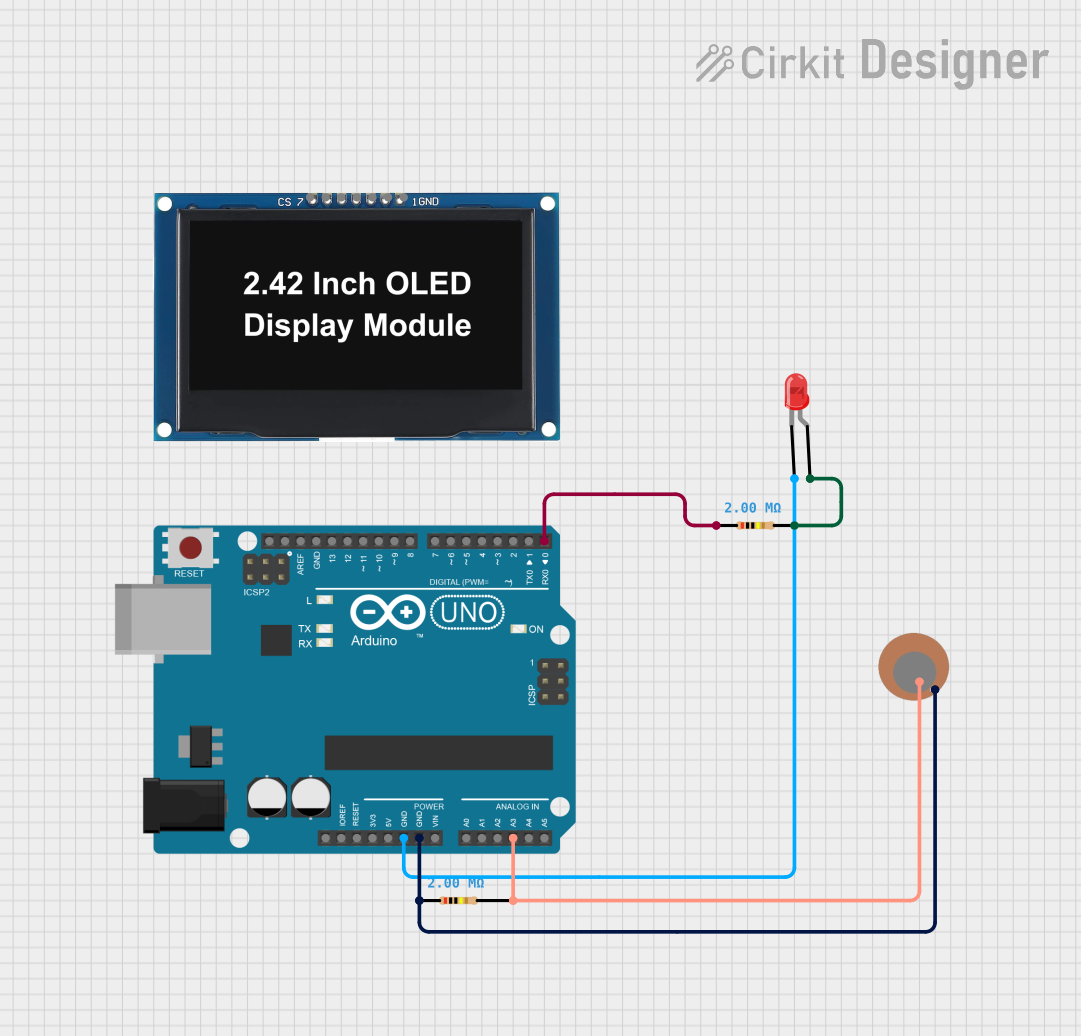
Circuit Documentation
Summary
This document provides a detailed overview of a circuit that includes an Arduino UNO microcontroller, a red two-pin LED, two resistors, a piezo sensor, and an OLED display. The circuit is designed to detect a threshold value from the piezo sensor and illuminate the LED when the threshold is exceeded. The Arduino UNO is used to read the sensor data and control the LED state.
Component List
Arduino UNO
- Microcontroller board based on the ATmega328P
- It has 14 digital input/output pins, 6 analog inputs, a 16 MHz quartz crystal, a USB connection, a power jack, an ICSP header, and a reset button.
LED: Two Pin (red)
- A simple red light-emitting diode with an anode and cathode for basic indication purposes.
Resistor (2x)
- Passive two-terminal electrical component that implements electrical resistance as a circuit element.
- Resistance: 2,000,000 Ohms (2 Megaohms)
Piezo Sensor
- A device that can detect pressure, force, or strain and convert it into an electrical charge.
OLED Display 2.42"
- A small display module with pins for power, communication, and control.
Wiring Details
Arduino UNO
- GND: Connected to the cathode of the LED and the negative (-) pin of the Piezo Sensor.
- A3: Connected to the positive (+) pin of the Piezo Sensor through a 2 Megaohm resistor.
- D0: Connected to one pin of a 2 Megaohm resistor, the other pin of which is connected to the anode of the LED.
LED: Two Pin (red)
- Cathode: Connected to the GND pin on the Arduino UNO.
- Anode: Connected to a 2 Megaohm resistor, which is then connected to pin D0 on the Arduino UNO.
Resistor (2x)
- One resistor is connected between the anode of the LED and pin D0 on the Arduino UNO.
- The other resistor is connected between the positive (+) pin of the Piezo Sensor and pin A3 on the Arduino UNO.
Piezo Sensor
- (+): Connected to pin A3 on the Arduino UNO through a 2 Megaohm resistor.
- (-): Connected to the GND pin on the Arduino UNO.
OLED Display 2.42"
- The OLED display wiring is not specified in the provided net list.
Documented Code
int sensoroutput = 3; // the analog pin connected to the sensor
int ledoutput = 0; // pin connected to LED
int THRESHOLD = 100;

void setup()
{
  pinMode(ledoutput, OUTPUT);   // this function is used to declare led connected pin as output
}

void loop()
{
  int value = analogRead(sensoroutput);  // function to read analog voltage from sensor
  if (value >= THRESHOLD)                    // function to check voltage level from sensor
  {
    digitalWrite(ledoutput, HIGH);
    delay(100); // to make the LED visible
  }
  else
  {
    digitalWrite(ledoutput, LOW);
  }
}
Filename: sketch.ino
Description: The code is written for an Arduino UNO microcontroller. It initializes a digital output pin for the LED and an analog input pin for the piezo sensor. In the main loop, the sensor's analog value is read and compared against a predefined threshold. If the value exceeds the threshold, the LED is turned on for a short period; otherwise, it is turned off.