
Circuit Documentation
Summary
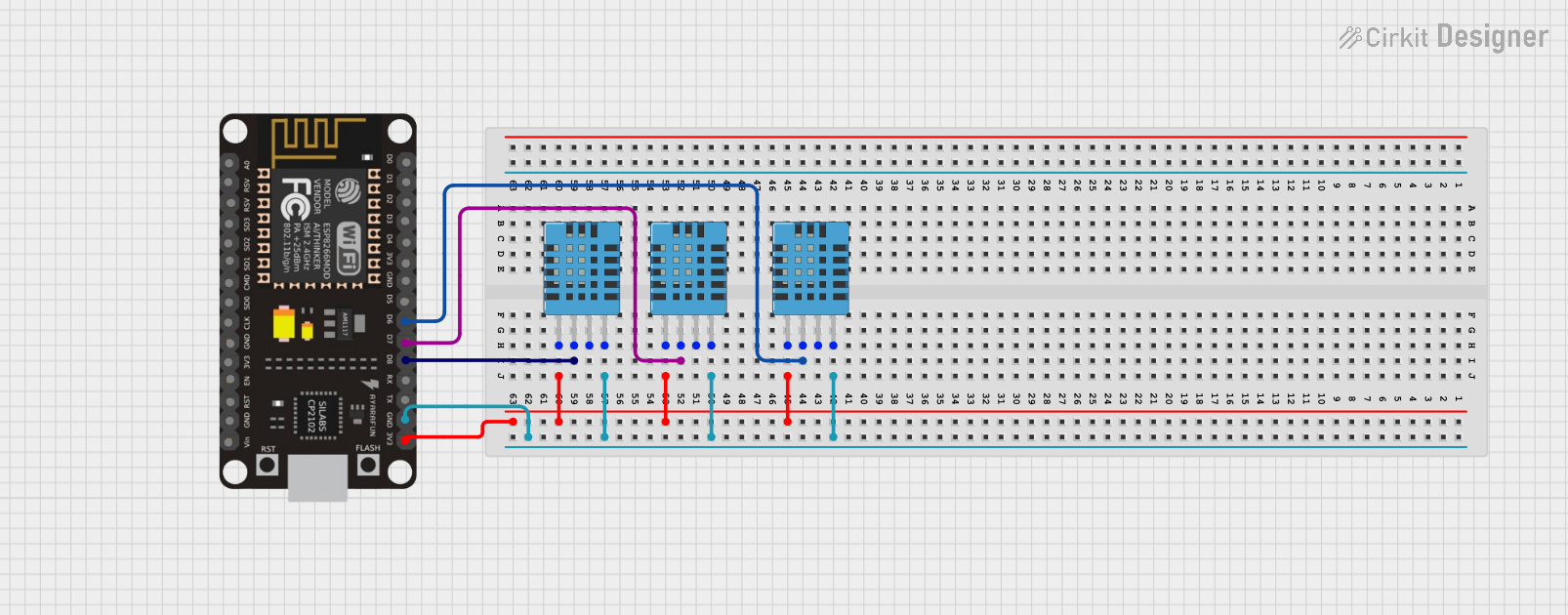
This circuit involves an ESP8266 NodeMCU microcontroller connected to three DHT11 Humidity and Temperature Sensors. The ESP8266 NodeMCU is responsible for reading data from the sensors and can be programmed to process or transmit this data as needed.
Component List
ESP8266 NodeMCU
- Description: A low-cost Wi-Fi microcontroller with GPIO, ADC, and other features.
- Pins: D0, D1, D2, D3, D4, 3V3, GND, D5, D6, D7, D8, RX, TX, A0, RSV, SD3, SD2, SD1, CMD, SD0, CLK, EN, RST, VIN
DHT11 Humidity and Temperature Sensor (x3)
- Description: A basic, low-cost digital temperature and humidity sensor.
- Pins: VDD, DATA, NULL, GND
Wiring Details
ESP8266 NodeMCU
- GND: Connected to GND of all DHT11 sensors.
- 3V3: Connected to VDD of all DHT11 sensors.
- D6: Connected to DATA of the first DHT11 sensor.
- D7: Connected to DATA of the second DHT11 sensor.
- D8: Connected to DATA of the third DHT11 sensor.
DHT11 Humidity and Temperature Sensor (1st)
- GND: Connected to GND of ESP8266 NodeMCU.
- VDD: Connected to 3V3 of ESP8266 NodeMCU.
- DATA: Connected to D6 of ESP8266 NodeMCU.
DHT11 Humidity and Temperature Sensor (2nd)
- GND: Connected to GND of ESP8266 NodeMCU.
- VDD: Connected to 3V3 of ESP8266 NodeMCU.
- DATA: Connected to D7 of ESP8266 NodeMCU.
DHT11 Humidity and Temperature Sensor (3rd)
- GND: Connected to GND of ESP8266 NodeMCU.
- VDD: Connected to 3V3 of ESP8266 NodeMCU.
- DATA: Connected to D8 of ESP8266 NodeMCU.
Documented Code
sketch.ino
void setup() {
  // put your setup code here, to run once:

}

void loop() {
  // put your main code here, to run repeatedly:

}
documentation.txt