
Arduino UNO-Based Smart Hall Management System with PIR Sensors and Temperature Control
View and Edit Project In Cirkit Designer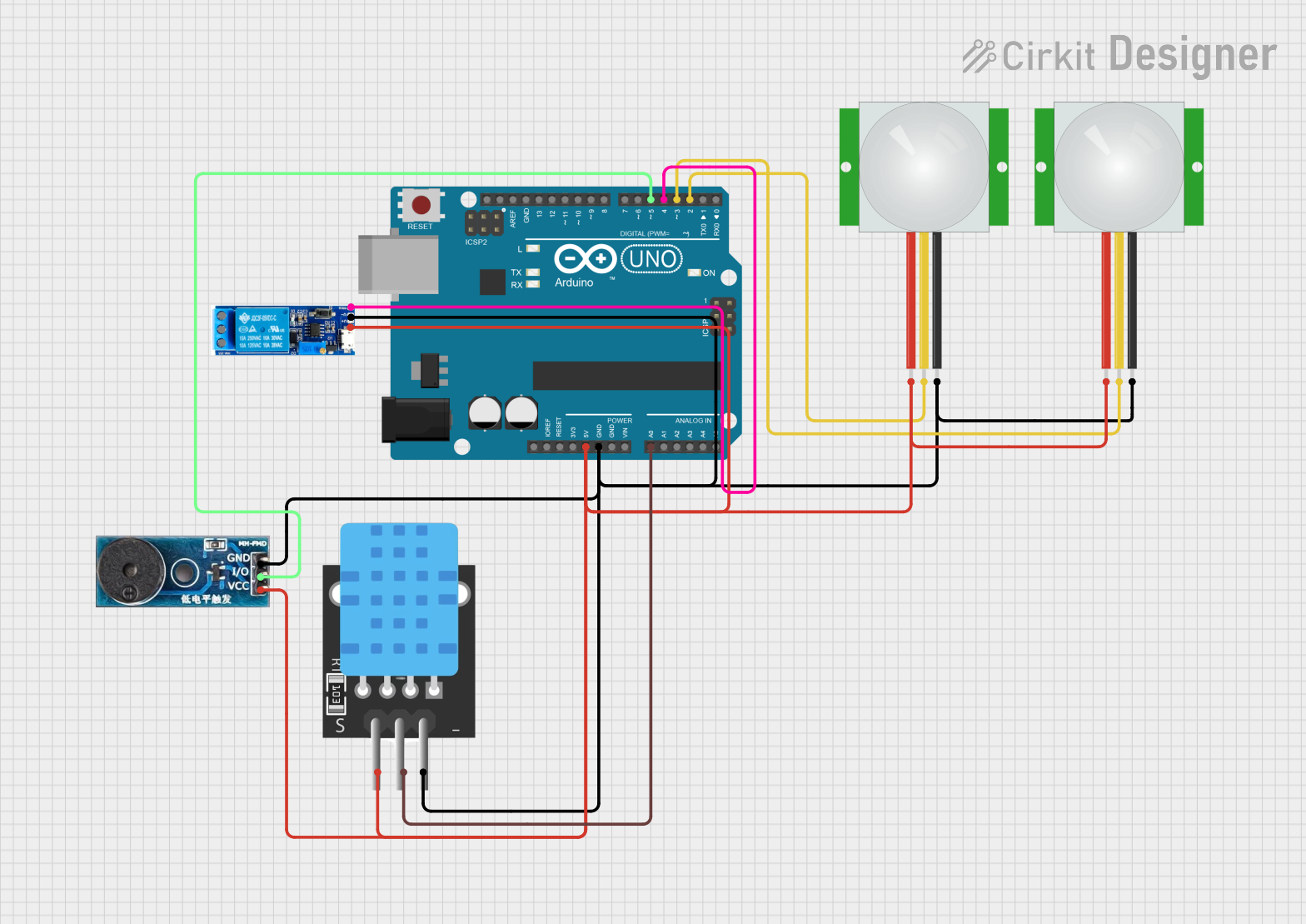
Circuit Documentation
Summary
This circuit is designed to monitor and control the environment of a hall. It includes sensors to detect entry and exit of people, a temperature sensor to monitor the hall's temperature, a relay module to control a chiller, and a buzzer module to provide alerts. The system is controlled by an Arduino UNO microcontroller.
Component List
Arduino UNO
- Description: Microcontroller board based on the ATmega328P.
- Pins: UNUSED, IOREF, Reset, 3.3V, 5V, GND, Vin, A0, A1, A2, A3, A4, A5, SCL, SDA, AREF, D13, D12, D11, D10, D9, D8, D7, D6, D5, D4, D3, D2, D1, D0
PIR Sensor (Entry)
- Description: Passive Infrared Sensor for detecting motion.
- Pins: VDD, SIG, GND
PIR Sensor (Exit)
- Description: Passive Infrared Sensor for detecting motion.
- Pins: VDD, SIG, GND
Temperature Sensor (TEMP)
- Description: Sensor for measuring temperature.
- Pins: 5V, D3, GND
Relay Module 5V-30V
- Description: Relay module for switching high voltage devices.
- Pins: common contact, normally open, normally closed, trigger, V-, V+
Buzzer Module
- Description: Module for generating sound alerts.
- Pins: GND, Vcc, I/O
Wiring Details
Arduino UNO
- 5V: Connected to VDD of both PIR sensors, V+ of Relay Module, Vcc of Buzzer Module, and 5V of Temperature Sensor.
- GND: Connected to GND of both PIR sensors, V- of Relay Module, GND of Buzzer Module, and GND of Temperature Sensor.
- A0: Connected to D3 of Temperature Sensor.
- D2: Connected to SIG of Exit PIR Sensor.
- D3: Connected to SIG of Entry PIR Sensor.
- D4: Connected to trigger of Relay Module.
- D5: Connected to I/O of Buzzer Module.
PIR Sensor (Entry)
- VDD: Connected to 5V of Arduino UNO.
- SIG: Connected to D3 of Arduino UNO.
- GND: Connected to GND of Arduino UNO.
PIR Sensor (Exit)
- VDD: Connected to 5V of Arduino UNO.
- SIG: Connected to D2 of Arduino UNO.
- GND: Connected to GND of Arduino UNO.
Temperature Sensor (TEMP)
- 5V: Connected to 5V of Arduino UNO.
- D3: Connected to A0 of Arduino UNO.
- GND: Connected to GND of Arduino UNO.
Relay Module 5V-30V
- V+: Connected to 5V of Arduino UNO.
- V-: Connected to GND of Arduino UNO.
- trigger: Connected to D4 of Arduino UNO.
Buzzer Module
- Vcc: Connected to 5V of Arduino UNO.
- GND: Connected to GND of Arduino UNO.
- I/O: Connected to D5 of Arduino UNO.
Code Documentation
#include <Wire.h>

// Pin definitions
#define ENTRY_SENSOR_PIN 2
#define EXIT_SENSOR_PIN 3
#define CHILLER_SWITCH_PIN 4
#define TEMP_SENSOR_PIN A0
#define BUZZER_PIN 5

// Constants
const int MAX_CAPACITY = 100;
const int REOPEN_THRESHOLD = 90;
const int TEMP_UPPER_LIMIT = 25; // Degrees Celsius
const int TEMP_LOWER_LIMIT = 24; // Degrees Celsius

// Variables
volatile int peopleInHall = 0;
bool chillerStatus = false;
int hallTemperature = 25;

// Structure to hold parameters
struct HallData {
  int temperature;
  bool chillerStatus;
  int numberOfPeople;
} hallData;

// Function prototypes
void entryDetected();
void exitDetected();
void updateTemperature();
void controlChiller();
void checkCapacity();
void publishData();

void setup() {
  Serial.begin(9600);

  // Pin configurations
  pinMode(ENTRY_SENSOR_PIN, INPUT_PULLUP);
  pinMode(EXIT_SENSOR_PIN, INPUT_PULLUP);
  pinMode(CHILLER_SWITCH_PIN, OUTPUT);
  pinMode(BUZZER_PIN, OUTPUT);

  // Attach interrupts
  attachInterrupt(digitalPinToInterrupt(ENTRY_SENSOR_PIN), entryDetected, FALLING);
  attachInterrupt(digitalPinToInterrupt(EXIT_SENSOR_PIN), exitDetected, FALLING);

  // Initial states
  digitalWrite(CHILLER_SWITCH_PIN, LOW);
  digitalWrite(BUZZER_PIN, LOW);

  Serial.println("System Initialized");
}

void loop() {
  // Fetch temperature data and update chiller status
  updateTemperature();
  controlChiller();

  // Check hall capacity and control alarms
  checkCapacity();

  // Publish data every minute
  static unsigned long lastPublishTime = 0;
  if (millis() - lastPublishTime >= 60000) { // 1-minute interval
    publishData();
    lastPublishTime = millis();
  }
}

void entryDetected() {
  if (peopleInHall < MAX_CAPACITY) {
    peopleInHall++;
  }
}

void exitDetected() {
  if (peopleInHall > 0) {
    peopleInHall--;
  }
}

void updateTemperature() {
  int sensorValue = analogRead(TEMP_SENSOR_PIN);
  hallTemperature = map(sensorValue, 0, 1023, 15, 35); // Simulate temperature range 15-35°C
}

void controlChiller() {
  if (hallTemperature > TEMP_UPPER_LIMIT && !chillerStatus) {
    chillerStatus = true;
    digitalWrite(CHILLER_SWITCH_PIN, HIGH);
  } else if (hallTemperature < TEMP_LOWER_LIMIT && chillerStatus) {
    chillerStatus = false;
    digitalWrite(CHILLER_SWITCH_PIN, LOW);
  }
}

void checkCapacity() {
  if (peopleInHall >= MAX_CAPACITY) {
    digitalWrite(BUZZER_PIN, HIGH); // Alarm ON
    Serial.println("Hall at maximum capacity! Entry gate closed.");
  } else if (peopleInHall <= REOPEN_THRESHOLD) {
    digitalWrite(BUZZER_PIN, LOW); // Alarm OFF
    Serial.println("Hall below reopen threshold. Entry gate reopened.");
  }
}

void publishData() {
  hallData.temperature = hallTemperature;
  hallData.chillerStatus = chillerStatus;
  hallData.numberOfPeople = peopleInHall;

  Serial.println("Publishing Data:");
  Serial.print("Temperature: ");
  Serial.print(hallData.temperature);
  Serial.println("°C");
  Serial.print("Chiller Status: ");
  Serial.println(hallData.chillerStatus ? "ON" : "OFF");
  Serial.print("Number of People: ");
  Serial.println(hallData.numberOfPeople);
}
This code is responsible for monitoring the entry and exit of people, controlling the chiller based on temperature readings, and providing alerts when the hall reaches its maximum capacity. The data is published every minute to the serial monitor.