
Arduino and ESP32-Based Smart Security System with Ultrasonic Sensor and GSM Module
View and Edit Project In Cirkit Designer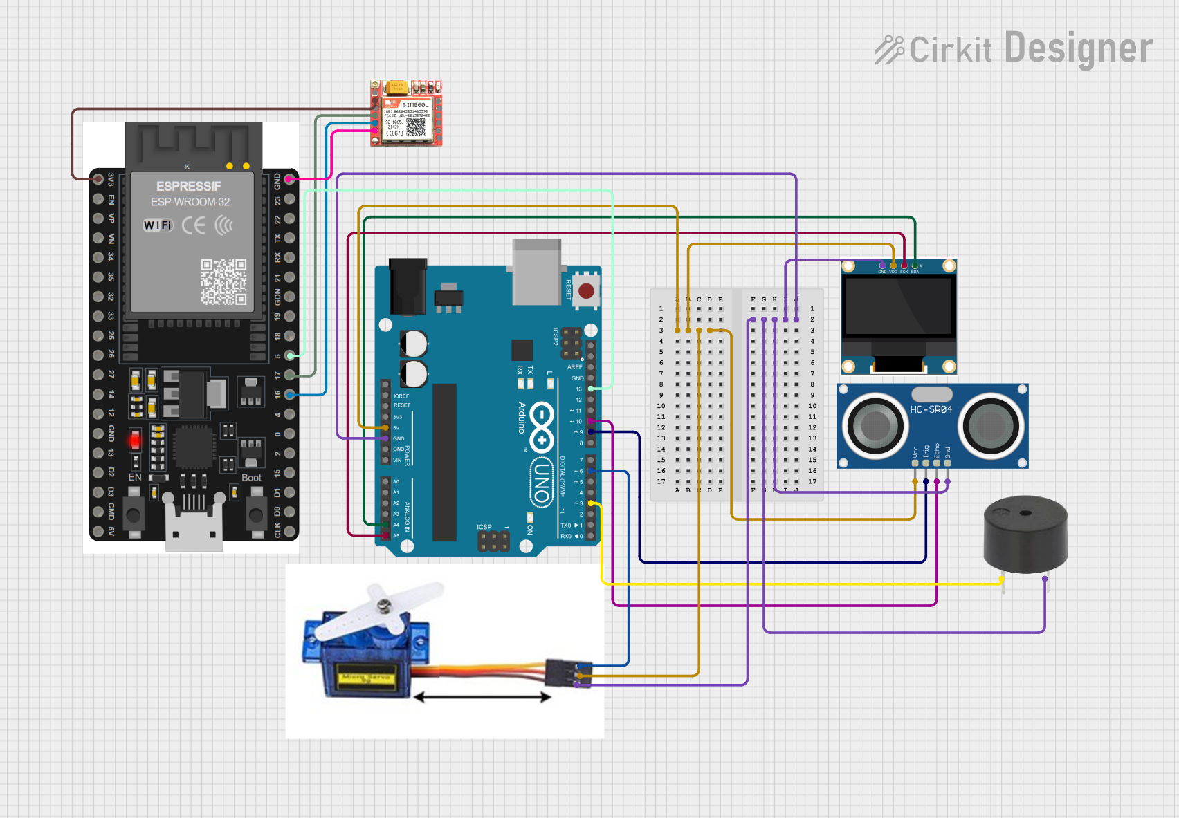
Circuit Documentation
Summary
This circuit integrates an Arduino UNO, an ESP32, an HC-SR04 Ultrasonic Sensor, a 0.96" OLED display, a Servo Motor 9G, a buzzer, and a SIM800L module. The Arduino UNO serves as the primary microcontroller, interfacing with the ultrasonic sensor, OLED display, servo motor, and buzzer. The ESP32 is used to communicate with the SIM800L module for sending SMS notifications.
Component List
Arduino UNO
- Description: A microcontroller board based on the ATmega328P.
- Pins: UNUSED, IOREF, Reset, 3.3V, 5V, GND, Vin, A0, A1, A2, A3, A4, A5, SCL, SDA, AREF, D13, D12, D11, D10, D9, D8, D7, D6, D5, D4, D3, D2, D1, D0
HC-SR04 Ultrasonic Sensor
- Description: A sensor used for measuring distance using ultrasonic waves.
- Pins: VCC, TRIG, ECHO, GND
0.96" OLED
- Description: A small OLED display for visual output.
- Pins: GND, VDD, SCK, SDA
Servo Motor 9G
- Description: A small servo motor used for precise control of angular position.
- Pins: VCC 5V, PMW, GND
Buzzer
- Description: An audio signaling device.
- Pins: PIN, GND
ESP32 38 PINS
- Description: A low-cost, low-power system on a chip microcontroller with integrated Wi-Fi and dual-mode Bluetooth.
- Pins: GND, 23, 22/SCL, 1, 2, 21/SDA, 19, 18, 5, 17/TX2, 16/RX2, 4, 0, 15, D1, D0, CLK, 3V3, EN, VP, VN, 34, 35, 32, 33, 25, 26, 27, 14, 12, 13, D2, D3, 11, 5V/VIN
SIM800L
- Description: A GSM/GPRS module used for communication over cellular networks.
- Pins: NFT, RING, VCC, DTR, RST, MIC +, RXD, MIC-, TXD, SPK+, GND, SPK-
Wiring Details
Arduino UNO
- 5V: Connected to VCC 5V of Servo Motor 9G, VDD of 0.96" OLED, and VCC of HC-SR04 Ultrasonic Sensor.
- GND: Connected to GND of Servo Motor 9G, GND of buzzer, GND of 0.96" OLED, and GND of HC-SR04 Ultrasonic Sensor.
- A4: Connected to SDA of 0.96" OLED.
- A5: Connected to SCK of 0.96" OLED.
- D13: Connected to pin 5 of ESP32.
- D10: Connected to ECHO of HC-SR04 Ultrasonic Sensor.
- D9: Connected to TRIG of HC-SR04 Ultrasonic Sensor.
- D6: Connected to PMW of Servo Motor 9G.
- D3: Connected to PIN of buzzer.
HC-SR04 Ultrasonic Sensor
- VCC: Connected to 5V of Arduino UNO.
- GND: Connected to GND of Arduino UNO.
- TRIG: Connected to D9 of Arduino UNO.
- ECHO: Connected to D10 of Arduino UNO.
0.96" OLED
- VDD: Connected to 5V of Arduino UNO.
- GND: Connected to GND of Arduino UNO.
- SDA: Connected to A4 of Arduino UNO.
- SCK: Connected to A5 of Arduino UNO.
Servo Motor 9G
- VCC 5V: Connected to 5V of Arduino UNO.
- GND: Connected to GND of Arduino UNO.
- PMW: Connected to D6 of Arduino UNO.
Buzzer
- PIN: Connected to D3 of Arduino UNO.
- GND: Connected to GND of Arduino UNO.
ESP32 38 PINS
- 5: Connected to D13 of Arduino UNO.
- GND: Connected to GND of SIM800L.
- 17/TX2: Connected to RXD of SIM800L.
- 16/RX2: Connected to TXD of SIM800L.
- 3V3: Connected to VCC of SIM800L.
SIM800L
- VCC: Connected to 3V3 of ESP32.
- GND: Connected to GND of ESP32.
- RXD: Connected to 17/TX2 of ESP32.
- TXD: Connected to 16/RX2 of ESP32.
Code Documentation
#include <HardwareSerial.h>

// Create a HardwareSerial instance
HardwareSerial sim800(2); // UART2: GPIO16 -> RX, GPIO17 -> TX

// Pin to check if it gets HIGH (D1 is GPIO5 on ESP32)
const int triggerPin = 5;

void setup() {
  // Initialize Serial Monitor
  Serial.begin(115200);

  // Initialize SIM800 module
  sim800.begin(9600, SERIAL_8N1, 16, 17); // baud rate: 9600, RX: GPIO16, TX: GPIO17
  delay(1000);

  // Send initialization commands to the SIM800
  sendATCommand("AT");            // Basic check
  sendATCommand("ATE0");          // Turn off echo
  sendATCommand("AT+CMGF=1");     // Set SMS mode to text
  sendATCommand("AT+CSCS=\"GSM\""); // Set character set

  // Initialize triggerPin as input
  pinMode(triggerPin, INPUT);
}

void loop() {
  // Check if the D1 pin (GPIO5) is HIGH
  if (digitalRead(triggerPin) == HIGH) {
    // Send the SMS if the pin is HIGH
    sendSMS("+918767716641", "Target Detected At :- https://maps.app.goo.gl/9Pw447xSRKxQdCa97");

    // Optional: Add a small delay to prevent sending multiple messages if the pin stays HIGH
    delay(10000);  // Wait for 10 seconds before checking again
  }
}

void sendATCommand(String command) {
  sim800.println(command);
  delay(500);
  while (sim800.available()) {
    String response = sim800.readString();
    Serial.println(response);
  }
}

void sendSMS(String phoneNumber, String message) {
  Serial.println("Sending SMS...");
  sim800.println("AT+CMGS=\"" + phoneNumber + "\"");
  delay(1000); // Wait for the module to be ready
  sim800.println(message);
  delay(500);
  sim800.write(26); // CTRL+Z to send the message
  delay(5000); // Wait for response

  while (sim800.available()) {
    String response = sim800.readString();
    Serial.println(response);
  }
}
This code initializes the SIM800L module and sets up a trigger pin to send an SMS when the pin goes HIGH. The sendATCommand function sends AT commands to the SIM800L, and the sendSMS function sends an SMS to a specified phone number.