Cirkit Designer
Your all-in-one circuit design IDE
Home /
Project Documentation
Arduino-Controlled RFID Authentication with Relay-Driven Gearmotor
Circuit Documentation
Summary
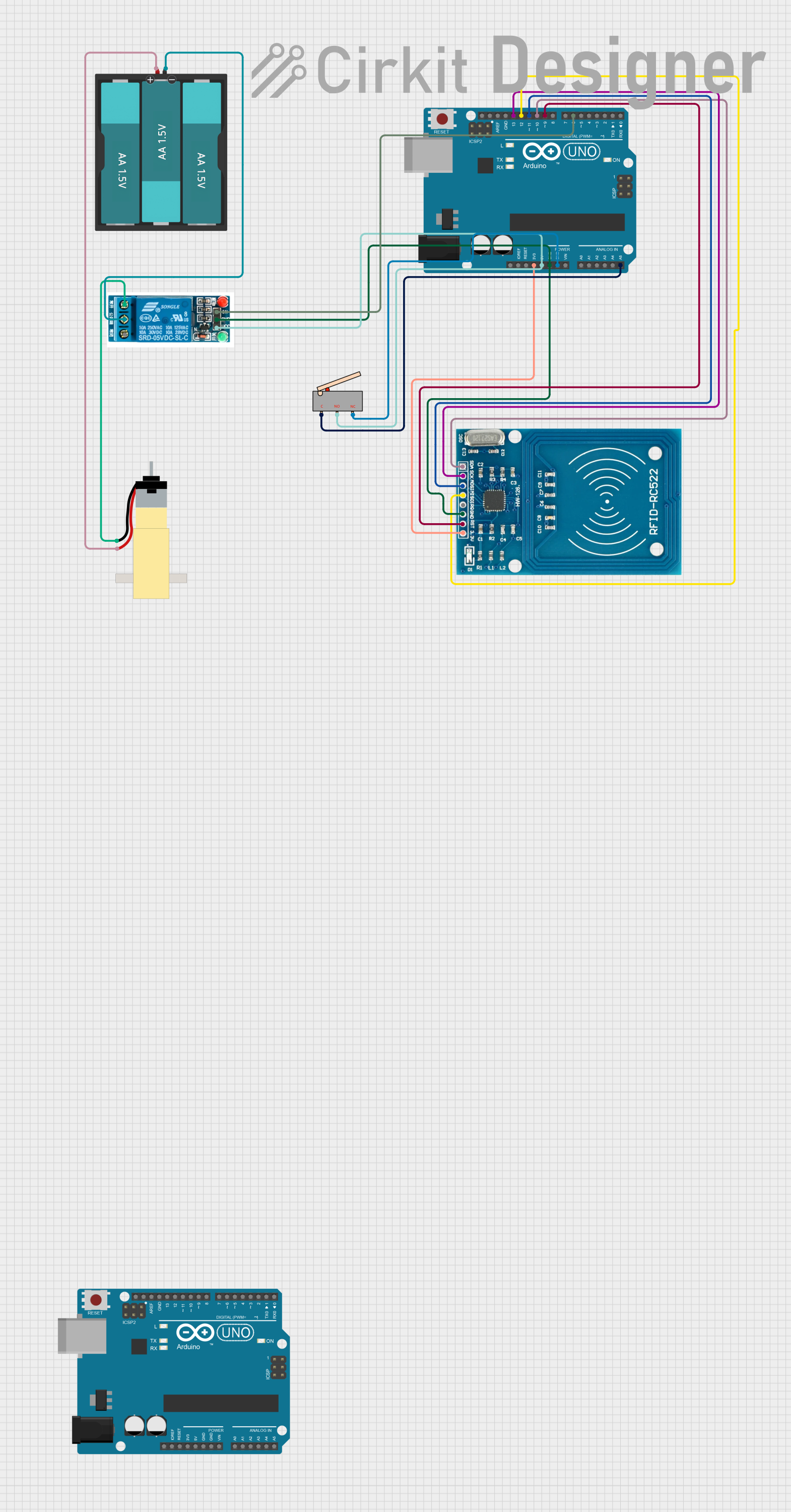
This circuit integrates an Arduino UNO microcontroller with an RFID-RC522 module, a limit switch, a 5V relay, and a hobby gearmotor powered by a 4.5V battery pack. The Arduino UNO is used as the central processing unit, interfacing with the RFID module for identification purposes and controlling the relay which in turn drives the gearmotor. The limit switch serves as an input device to the Arduino, providing a means to trigger events when activated.
Component List
Arduino UNO
- Microcontroller board based on the ATmega328P
- Digital I/O Pins: 14 (of which 6 provide PWM output)
- Analog Input Pins: 6
- Operating Voltage: 5V
Limit Switch
- A switch that is actuated by the motion of a machine part or presence of an object
- Pins: Common (C), Normally Open (NO), Normally Closed (NC)
Battery AAx3 4.5V
- A battery pack consisting of three AA cells in series
- Output Voltage: 4.5V
Hobby Gearmotor with 48:1 Gearbox
- A DC motor with an attached gearbox to reduce speed and increase torque
- Operating Voltage: Typically around 6V
RFID-RC522
- An RFID reader/writer module
- Operating Voltage: 3.3V
5V Relay
- An electromechanical switch used to control a high power circuit with a low power signal
- Pins: Normally Open (NO), Common terminal (COM), Normally Closed (NC), Input (In), Ground (GND), Voltage Supply (VCC)
Wiring Details
Arduino UNO
3.3Vconnected to RFID-RC522 VCC (3.3V)D9connected to RFID-RC522 RSTGNDconnected to RFID-RC522 GND, 5V relay GND, and Limit switch NCD12connected to RFID-RC522 MISOD11connected to RFID-RC522 MOSID13connected to RFID-RC522 SCKD10connected to RFID-RC522 SDA5Vconnected to Limit switch NO and 5V relay VCCA5connected to Limit switch CD6connected to 5V relay In
Limit Switch
NOconnected to Arduino UNO 5VNCconnected to Arduino UNO GNDCconnected to Arduino UNO A5
Battery AAx3 4.5V
GNDconnected to 5V relay Common terminalVCCconnected to Hobby Gearmotor pin 2
Hobby Gearmotor with 48:1 Gearbox
pin 1connected to 5V relay Normally Openpin 2connected to Battery AAx3 4.5V VCC
RFID-RC522
VCC (3.3V)connected to Arduino UNO 3.3VRSTconnected to Arduino UNO D9GNDconnected to Arduino UNO GNDMISOconnected to Arduino UNO D12MOSIconnected to Arduino UNO D11SCKconnected to Arduino UNO D13SDAconnected to Arduino UNO D10
5V Relay
GNDconnected to Arduino UNO GNDVCCconnected to Arduino UNO 5VInconnected to Arduino UNO D6Normally Openconnected to Hobby Gearmotor pin 1Common terminalconnected to Battery AAx3 4.5V GND
Documented Code
Arduino UNO Code (Primary Controller)
void setup() {
  // put your setup code here, to run once:

}

void loop() {
  // put your main code here, to run repeatedly:

}
Arduino UNO Code (Secondary Controller)
void setup() {
  // put your setup code here, to run once:

}

void loop() {
  // put your main code here, to run repeatedly:

}
Note: The actual functionality of the code is not provided in the input and should be implemented according to the specific requirements of the circuit's operation.