
Arduino Controlled Solenoid Activation with MOSFET Switching
View and Edit Project In Cirkit Designer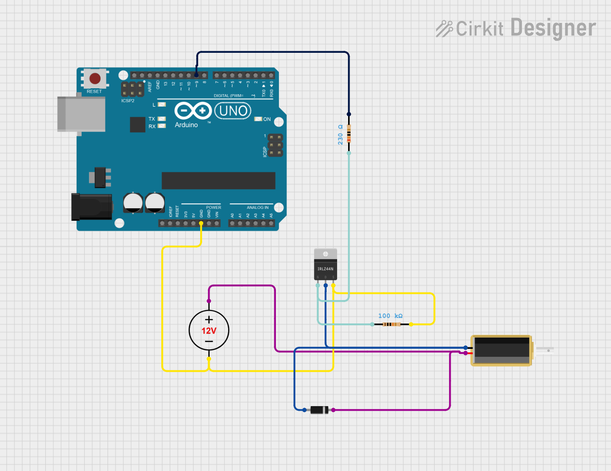
Circuit Documentation
Summary
This circuit is designed to control a solenoid using a MOSFET as a switch, with an Arduino UNO microcontroller managing the activation and deactivation of the solenoid. The solenoid is powered by a 12V DC power supply. The circuit includes resistors for current limiting and a diode for flyback protection to prevent voltage spikes when the solenoid is turned off.
Component List
1. Arduino UNO
- Description: A microcontroller board based on the ATmega328P.
- Purpose: Acts as the control unit for the circuit, managing the MOSFET gate to activate the solenoid.
2. 12V DC Power Supply
- Description: Provides a 12V power source for the solenoid.
- Purpose: Supplies the necessary voltage to operate the solenoid.
3. MOSFET
- Description: A type of transistor used for switching and amplifying electronic signals.
- Purpose: Acts as a switch to control the solenoid based on the signal from the Arduino.
4. Resistor (230 Ohms)
- Description: A passive electrical component that resists the flow of current.
- Purpose: Used to limit the current to the MOSFET gate.
5. Diode
- Description: A semiconductor device that allows current to flow in one direction only.
- Purpose: Provides flyback protection for the circuit by preventing voltage spikes from the solenoid.
6. Solenoid
- Description: An electromechanical device that converts electrical energy into linear motion.
- Purpose: Performs mechanical work by moving a plunger when energized.
7. Resistor (100k Ohms)
- Description: A passive electrical component that resists the flow of current.
- Purpose: Used for pull-down or current limiting in the circuit.
Wiring Details
Arduino UNO
GND connected to:
- 12V DC Power Supply (Negative)
- Resistor (100k Ohms, pin2)
- MOSFET (Source)
D9 connected to:
- Resistor (230 Ohms, pin2)
12V DC Power Supply
Positive connected to:
- Solenoid (Positive)
- Diode (cathode)
Negative connected to:
- Arduino UNO (GND)
- Resistor (100k Ohms, pin2)
- MOSFET (Source)
MOSFET
Gate connected to:
- Resistor (230 Ohms, pin1)
Drain connected to:
- Solenoid (Negative)
- Diode (anode)
Source connected to:
- Arduino UNO (GND)
- 12V DC Power Supply (Negative)
Resistor (230 Ohms)
pin1 connected to:
- MOSFET (Gate)
pin2 connected to:
- Arduino UNO (D9)
Resistor (100k Ohms)
pin1 connected to:
- Arduino UNO (GND)
pin2 connected to:
- MOSFET (Gate)
Diode
cathode connected to:
- Solenoid (Positive)
- 12V DC Power Supply (Positive)
anode connected to:
- MOSFET (Drain)
Solenoid
Positive connected to:
- 12V DC Power Supply (Positive)
- Diode (cathode)
Negative connected to:
- MOSFET (Drain)
Documented Code
/*
 * Arduino Sketch to test a solenoid using a MOSFET as a switch.
 * The MOSFET gate is controlled by pin D9 of the Arduino UNO.
 * The solenoid is powered by a 12V DC power supply.
 * This code will activate the solenoid for 1 second and then deactivate it
 * for 1 second, repeatedly.
 */

const int mosfetGatePin = 9; // Pin connected to the MOSFET gate

void setup() {
  // Initialize the MOSFET gate pin as an output
  pinMode(mosfetGatePin, OUTPUT);
  digitalWrite(mosfetGatePin, LOW);
}

void loop() {
  // Activate the solenoid
  digitalWrite(mosfetGatePin, HIGH);
  delay(1000); // Wait for 1 second

  // Deactivate the solenoid
  digitalWrite(mosfetGatePin, LOW);
  delay(1000); // Wait for 1 second
}
This documentation provides a comprehensive overview of the circuit, detailing each component, its purpose, and the wiring connections, along with the Arduino code used to control the solenoid.