
Arduino Mega 2560-Based Fire and Gas Detection System with Automated Water Pump
View and Edit Project In Cirkit Designer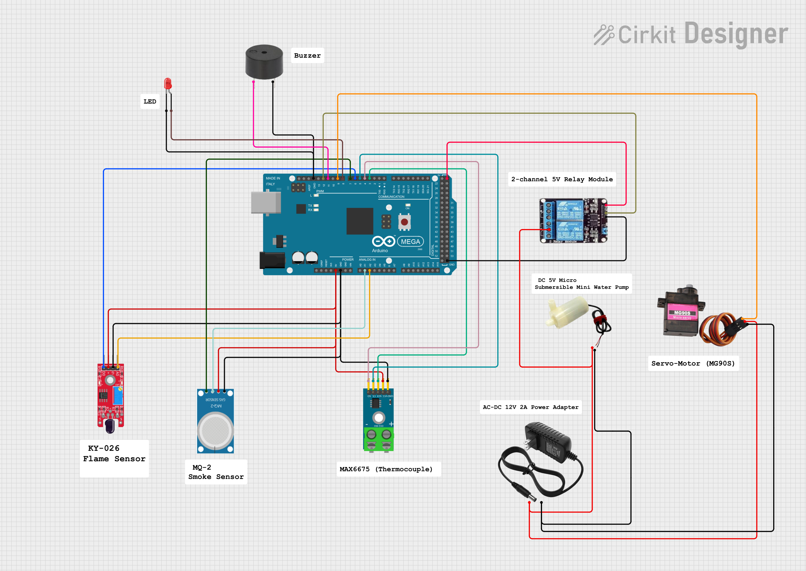
Circuit Documentation
Summary
This circuit is designed using an Arduino Mega 2560 microcontroller to interface with various sensors and actuators. The components include a flame sensor, gas sensor, temperature sensor, buzzer, LED, relay, water pump, and servo motor. The circuit is powered by a 12V power supply, and the Arduino Mega 2560 provides the necessary control signals to the connected components.
Component List
Arduino Mega 2560
- Description: A microcontroller board based on the ATmega2560.
- Pins: IOREF, RESET, 3V3, 5V, GND, VIN, A0-A15, D0-D53, AREF, SDA, SCL
KY-026 Flame Sensor
- Description: A sensor module for detecting flame.
- Pins: AO, GND, VCC, DO
MQ-2 Gas Sensor
- Description: A sensor module for detecting gas.
- Pins: GND, VCC, ANALOG, Digital
MAX6675 Module
- Description: A module for measuring temperature using a thermocouple.
- Pins: GND, VCC, SCK, CS, SO, -, +
Buzzer
- Description: An electronic device that emits sound.
- Pins: PIN, GND
LED: Two Pin (red)
- Description: A red LED with two pins.
- Pins: cathode, anode
2ch Relay
- Description: A two-channel relay module.
- Pins: NC, COM, NO, VCC, IN2, IN1, GND
5V Mini Water Pump
- Description: A small water pump operating at 5V.
- Pins: positive pin, negative pin
12V Power Supply
- Description: A power supply providing 12V.
- Pins: +, -
MG90S Servo Motor
- Description: A small servo motor.
- Pins: SIG, VCC, GND
Wiring Details
Arduino Mega 2560
5V connected to:
- KY-026 Flame Sensor (VCC)
- MAX6675 Module (VCC)
- MQ-2 Gas Sensor (VCC)
- 2ch Relay (VCC)
GND connected to:
- KY-026 Flame Sensor (GND)
- MAX6675 Module (GND)
- MQ-2 Gas Sensor (GND)
- Buzzer (GND)
- LED: Two Pin (red) (cathode)
- 2ch Relay (GND)
A1 connected to:
- MQ-2 Gas Sensor (ANALOG)
A2 connected to:
- KY-026 Flame Sensor (AO)
D3 PWM connected to:
- MAX6675 Module (SCK)
D4 PWM connected to:
- MAX6675 Module (SO)
D5 PWM connected to:
- MAX6675 Module (CS)
D6 PWM connected to:
- KY-026 Flame Sensor (DO)
D7 PWM connected to:
- MQ-2 Gas Sensor (Digital)
D8 PWM connected to:
- LED: Two Pin (red) (anode)
D9 PWM connected to:
- MG90S Servo Motor (SIG)
D11 PWM connected to:
- Buzzer (PIN)
D12 PWM connected to:
- 2ch Relay (IN1)
KY-026 Flame Sensor
VCC connected to:
- Arduino Mega 2560 (5V)
GND connected to:
- Arduino Mega 2560 (GND)
AO connected to:
- Arduino Mega 2560 (A2)
DO connected to:
- Arduino Mega 2560 (D6 PWM)
MQ-2 Gas Sensor
VCC connected to:
- Arduino Mega 2560 (5V)
GND connected to:
- Arduino Mega 2560 (GND)
ANALOG connected to:
- Arduino Mega 2560 (A1)
Digital connected to:
- Arduino Mega 2560 (D7 PWM)
MAX6675 Module
VCC connected to:
- Arduino Mega 2560 (5V)
GND connected to:
- Arduino Mega 2560 (GND)
SCK connected to:
- Arduino Mega 2560 (D3 PWM)
SO connected to:
- Arduino Mega 2560 (D4 PWM)
CS connected to:
- Arduino Mega 2560 (D5 PWM)
Buzzer
PIN connected to:
- Arduino Mega 2560 (D11 PWM)
GND connected to:
- Arduino Mega 2560 (GND)
LED: Two Pin (red)
anode connected to:
- Arduino Mega 2560 (D8 PWM)
cathode connected to:
- Arduino Mega 2560 (GND)
2ch Relay
VCC connected to:
- Arduino Mega 2560 (5V)
GND connected to:
- Arduino Mega 2560 (GND)
IN1 connected to:
- Arduino Mega 2560 (D12 PWM)
COM connected to:
- 12V Power Supply (+)
5V Mini Water Pump
positive pin connected to:
- 12V Power Supply (+)
negative pin connected to:
- 12V Power Supply (-)
12V Power Supply
+ connected to:
- 5V Mini Water Pump (positive pin)
- MG90S Servo Motor (VCC)
- 2ch Relay (COM)
- connected to:
- 5V Mini Water Pump (negative pin)
- MG90S Servo Motor (GND)
MG90S Servo Motor
SIG connected to:
- Arduino Mega 2560 (D9 PWM)
VCC connected to:
- 12V Power Supply (+)
GND connected to:
- 12V Power Supply (-)
Documented Code
sketch.ino
void setup() {
  // put your setup code here, to run once:

}

void loop() {
  // put your main code here, to run repeatedly:

}
documentation.txt