Arduino-Controlled Robotic System with Bluetooth Interface and Motorized Actuators
Circuit Documentation
Summary
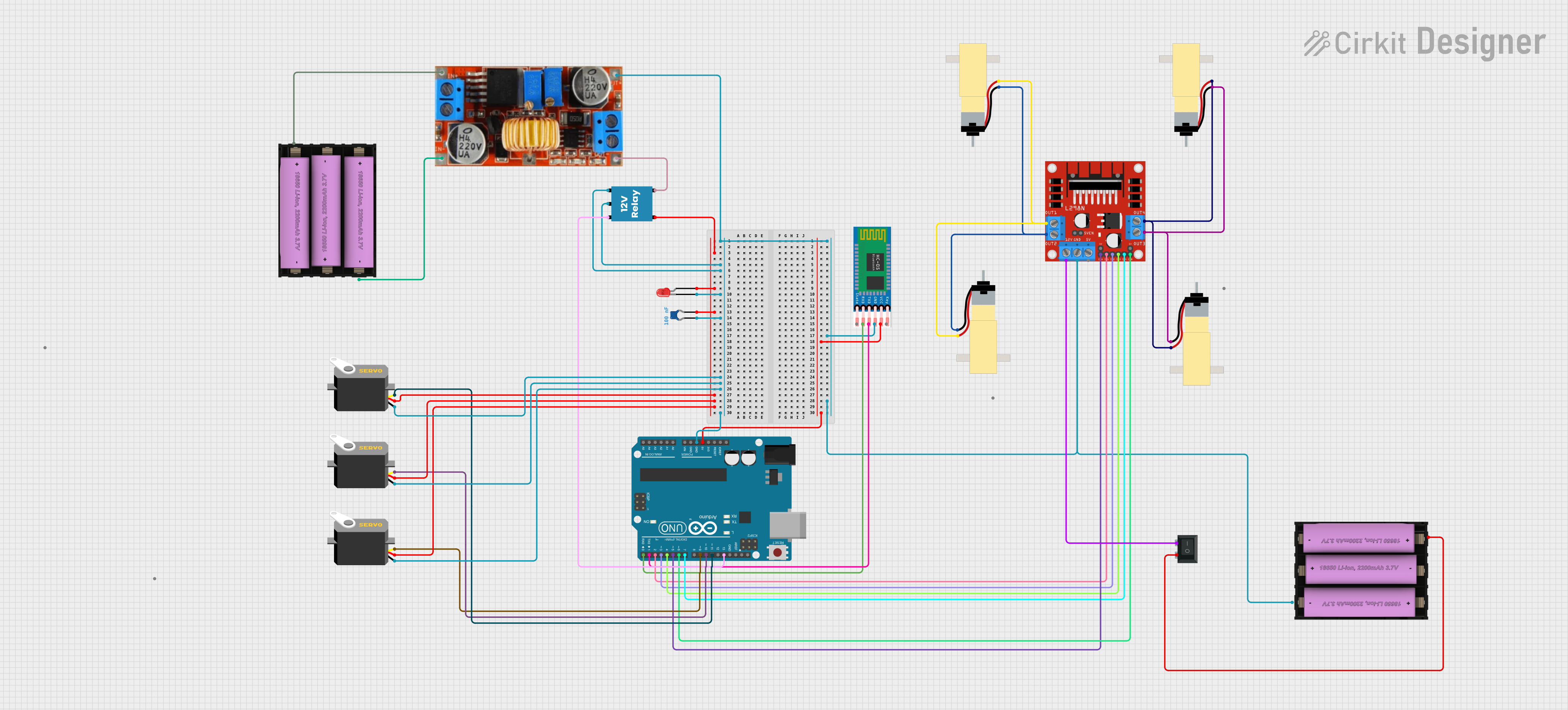
This document provides a detailed overview of a circuit designed to control servos, drive hobby gearmotors, and interface with a Bluetooth module (HC-05) for potential wireless control. The circuit is powered by Li-ion batteries and includes a voltage regulation system to step down the voltage for certain components. A microcontroller (Arduino UNO) is used to control the servos and motors via a motor driver (L298N) and to communicate with the HC-05 Bluetooth module. A relay is used to switch higher power loads, and an LED with a capacitor is included, possibly for status indication.
Component List
Servos
- Component: Servo
- Description: Actuator that can be precisely controlled in terms of the angle of rotation.
- Purpose: To provide controlled movement for various parts of the system.
Hobby Gearmotors
- Component: Hobby Gearmotor with 48:1 gearbox
- Description: A motor with a gearbox to provide high torque at lower speeds.
- Purpose: To drive mechanical parts of the system.
Rocker Switch (SPST)
- Component: Rocker Switch (SPST)
- Description: A single-pole single-throw switch to control power flow.
- Purpose: To serve as an on/off switch for the circuit.
Li-ion Batteries
- Component: Li-ion battery, 2200 mAh 11.1 V
- Description: A rechargeable battery providing a voltage of 11.1V.
- Purpose: To supply power to the circuit.
HC-05 Bluetooth Module
- Component: HC-05
- Description: A commonly used Bluetooth module for wireless communication.
- Purpose: To enable wireless control of the system.
L298N DC Motor Driver
- Component: L298N DC motor driver
- Description: A module capable of driving two DC motors with direction and speed control.
- Purpose: To control the direction and speed of the gearmotors.
XL4015 Step Down Voltage Converter
- Component: XL4015 step down bulk converter
- Description: A DC-DC converter that steps down voltage to a lower level.
- Purpose: To provide the appropriate voltage levels to components that require less than the battery voltage.
Relay
- Component: 12V Relay
- Description: An electromechanical switch that can control a large current with a small current.
- Purpose: To switch higher power loads on and off.
LED
- Component: LED: Two Pin (red)
- Description: A light-emitting diode that produces red light.
- Purpose: To indicate the status or provide visual feedback.
Capacitor
- Component: Ceramic Capacitor
- Description: A passive electronic component with a capacitance of 100nF.
- Purpose: To filter noise or provide power smoothing.
Microcontroller
- Component: Arduino UNO
- Description: A microcontroller board based on the ATmega328P.
- Purpose: To control the servos, motor driver, and communicate with the HC-05 module.
Wiring Details
Servos
- Ground: Connected to the system ground net.
- VCC: Connected to the positive voltage net.
- Pulse: Each servo pulse pin is connected to a dedicated digital pin on the Arduino UNO for control signals.
Hobby Gearmotors
- Pins 1 & 2: Each motor's pins are connected to the L298N motor driver's output pins.
Rocker Switch (SPST)
- Pins 1 & 2: One pin is connected to the positive terminal of the Li-ion battery, and the other is connected to the 12V input of the L298N motor driver.
Li-ion Batteries
- Positive (+) & Negative (-): The batteries are connected to provide power to the circuit, with one battery also connected to the input of the XL4015 voltage converter.
HC-05 Bluetooth Module
- EN, VCC, GND, TXD, RXD, STATE: The VCC and GND are connected to the 5V and ground nets, respectively. TXD and RXD are connected to the Arduino UNO for serial communication.
L298N DC Motor Driver
- IN1, IN2, IN3, IN4, ENA, ENB, OUT1, OUT2, OUT3, OUT4, GND, 12V: The input pins are connected to the Arduino UNO for control signals, the output pins to the motors, GND to the system ground net, and 12V to the power net through the rocker switch.
XL4015 Step Down Voltage Converter
- Input (+) & Input (-): Connected to the second Li-ion battery.
- Output (+) & Output (-): The output positive is connected to the relay's common (C) terminal and the output negative to the system ground net.
Relay
- +, -, C, NC, NO: The coil pins (+ and -) are connected to the Arduino UNO and system ground net, respectively. The common (C) is connected to the output of the voltage converter, normally closed (NC) to the LED and capacitor, and normally open (NO) to the system ground net.
LED
- Cathode & Anode: The cathode is connected to the system ground net, and the anode is connected to the normally closed (NC) terminal of the relay.
Capacitor
- Pins 0 & 1: Connected across the LED to provide noise filtering or power smoothing.
Arduino UNO
- Digital Pins (D0-D13), Analog Pins (A0-A5), 5V, GND: Digital pins are used for control signals to the servos, motor driver, and HC-05 module. The 5V and GND pins are used to power the HC-05 module.
Documented Code
Arduino UNO Code (sketch.ino)
void setup() {
  // put your setup code here, to run once:

}

void loop() {
  // put your main code here, to run repeatedly:

}
Note: The provided code is a template and does not contain any functional code. It needs to be populated with the logic to control the servos, motors, and handle communication with the HC-05 Bluetooth module.
Additional Notes
- The code for the microcontrollers with instance IDs
bda0a4fc-18ee-4f66-b2c0-d6ea77267e5eande536ef57-24f5-488a-92c2-77424b2a7892is identical to the Arduino UNO code and is not repeated here. - The
documentation.txtfiles for the microcontrollers are empty and thus not included in this document.