
Arduino and ESP8266-Based RFID Access Control System with LCD Display and Buzzer
View and Edit Project In Cirkit Designer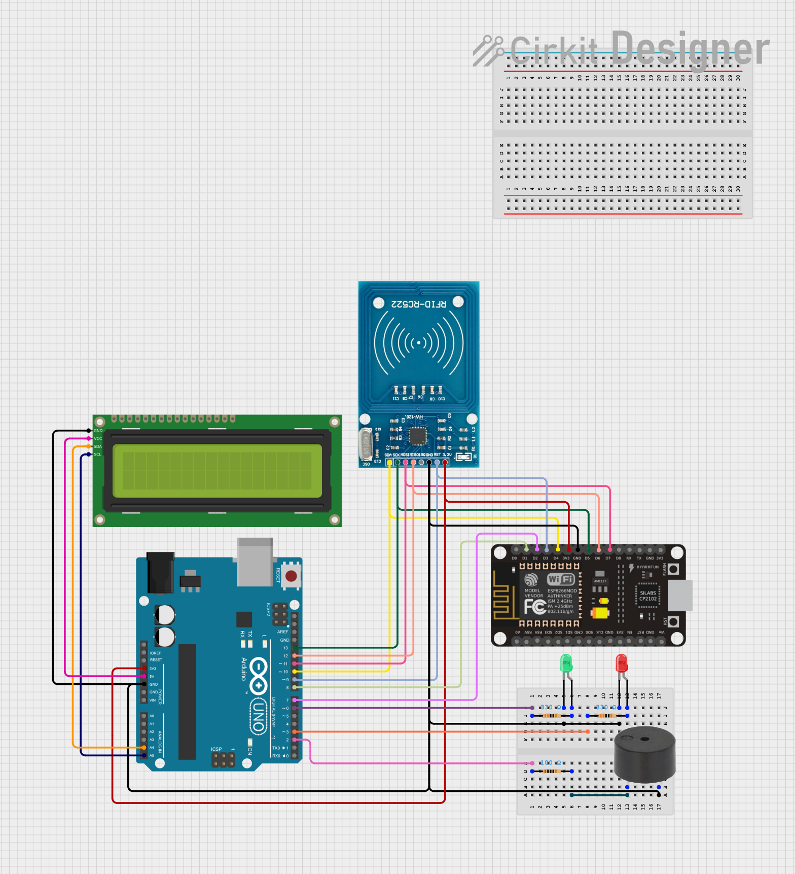
Circuit Documentation
Summary
This circuit involves an Arduino UNO microcontroller interfacing with various components including resistors, LEDs, a buzzer, an ESP8266 NodeMCU, a 16x2 I2C LCD, and an RFID-RC522 module. The circuit is designed to demonstrate basic interfacing and control of these components using the Arduino platform.
Component List
Resistor
- Description: A passive electrical component that implements electrical resistance as a circuit element.
- Pins: pin1, pin2
- Properties:
- Resistance: 100 Ohms
Resistor
- Description: A passive electrical component that implements electrical resistance as a circuit element.
- Pins: pin1, pin2
- Properties:
- Resistance: 330 Ohms
LED: Two Pin (red)
- Description: A red light-emitting diode.
- Pins: cathode, anode
LED: Two Pin (green)
- Description: A green light-emitting diode.
- Pins: cathode, anode
Buzzer
- Description: An audio signaling device.
- Pins: PIN, GND
ESP8266 NodeMCU
- Description: A low-cost Wi-Fi microchip with full TCP/IP stack and microcontroller capability.
- Pins: D0, D1, D2, D3, D4, 3V3, GND, D5, D6, D7, D8, RX, TX, A0, RSV, SD3, SD2, SD1, CMD, SD0, CLK, EN, RST, VIN
16x2 I2C LCD
- Description: A 16x2 character LCD display with I2C interface.
- Pins: GND, VCC, SDA, SCL
RFID-RC522
- Description: A low-cost RFID reader module.
- Pins: VCC (3.3V), RST, GND, IRQ, MISO, MOSI, SCK, SDA
Arduino UNO
- Description: A microcontroller board based on the ATmega328P.
- Pins: UNUSED, IOREF, Reset, 3.3V, 5V, GND, Vin, A0, A1, A2, A3, A4, A5, SCL, SDA, AREF, D13, D12, D11, D10, D9, D8, D7, D6, D5, D4, D3, D2, D1, D0
Wiring Details
Resistor (100 Ohms)
- pin1 connected to Arduino UNO D2
- pin2 connected to Buzzer PIN
Resistor (330 Ohms)
- pin1 connected to Arduino UNO D6
- pin2 connected to LED: Two Pin (green) anode
Resistor (330 Ohms)
- pin1 connected to Arduino UNO D3
- pin2 connected to LED: Two Pin (red) anode
LED: Two Pin (red)
- cathode connected to GND
- anode connected to Resistor pin2
LED: Two Pin (green)
- cathode connected to GND
- anode connected to Resistor pin2
Buzzer
- PIN connected to Resistor pin2
- GND connected to GND
ESP8266 NodeMCU
- 3V3 connected to Arduino UNO 3.3V
- GND connected to GND
- D5 connected to Arduino UNO D13
- D6 connected to Arduino UNO D12
- D7 connected to Arduino UNO D11
- D4 connected to Arduino UNO D10
- D3 connected to Arduino UNO D9
- D1 connected to Arduino UNO D8
- D2 connected to Arduino UNO D7
16x2 I2C LCD
- GND connected to GND
- VCC connected to Arduino UNO 5V
- SDA connected to Arduino UNO A4
- SCL connected to Arduino UNO A5
RFID-RC522
- VCC (3.3V) connected to Arduino UNO 3.3V
- GND connected to GND
- SCK connected to ESP8266 NodeMCU D5
- MISO connected to ESP8266 NodeMCU D6
- MOSI connected to ESP8266 NodeMCU D7
- SDA connected to ESP8266 NodeMCU D4
- RST connected to ESP8266 NodeMCU D3
Arduino UNO
- 3.3V connected to ESP8266 NodeMCU 3V3
- 5V connected to 16x2 I2C LCD VCC
- GND connected to GND
- D2 connected to Resistor pin1
- D3 connected to Resistor pin1
- D6 connected to Resistor pin1
- D7 connected to ESP8266 NodeMCU D2
- D8 connected to ESP8266 NodeMCU D1
- D9 connected to ESP8266 NodeMCU D3
- D10 connected to ESP8266 NodeMCU D4
- D11 connected to ESP8266 NodeMCU D7
- D12 connected to ESP8266 NodeMCU D6
- D13 connected to ESP8266 NodeMCU D5
- A4 connected to 16x2 I2C LCD SDA
- A5 connected to 16x2 I2C LCD SCL
Documented Code
Arduino UNO Code (sketch.ino)
void setup() {
  // put your setup code here, to run once:

}

void loop() {
  // put your main code here, to run repeatedly:

}
Documentation (documentation.txt)