
Arduino UNO and ESP8266 Wi-Fi Enabled Load Cell Weight Measurement System
View and Edit Project In Cirkit Designer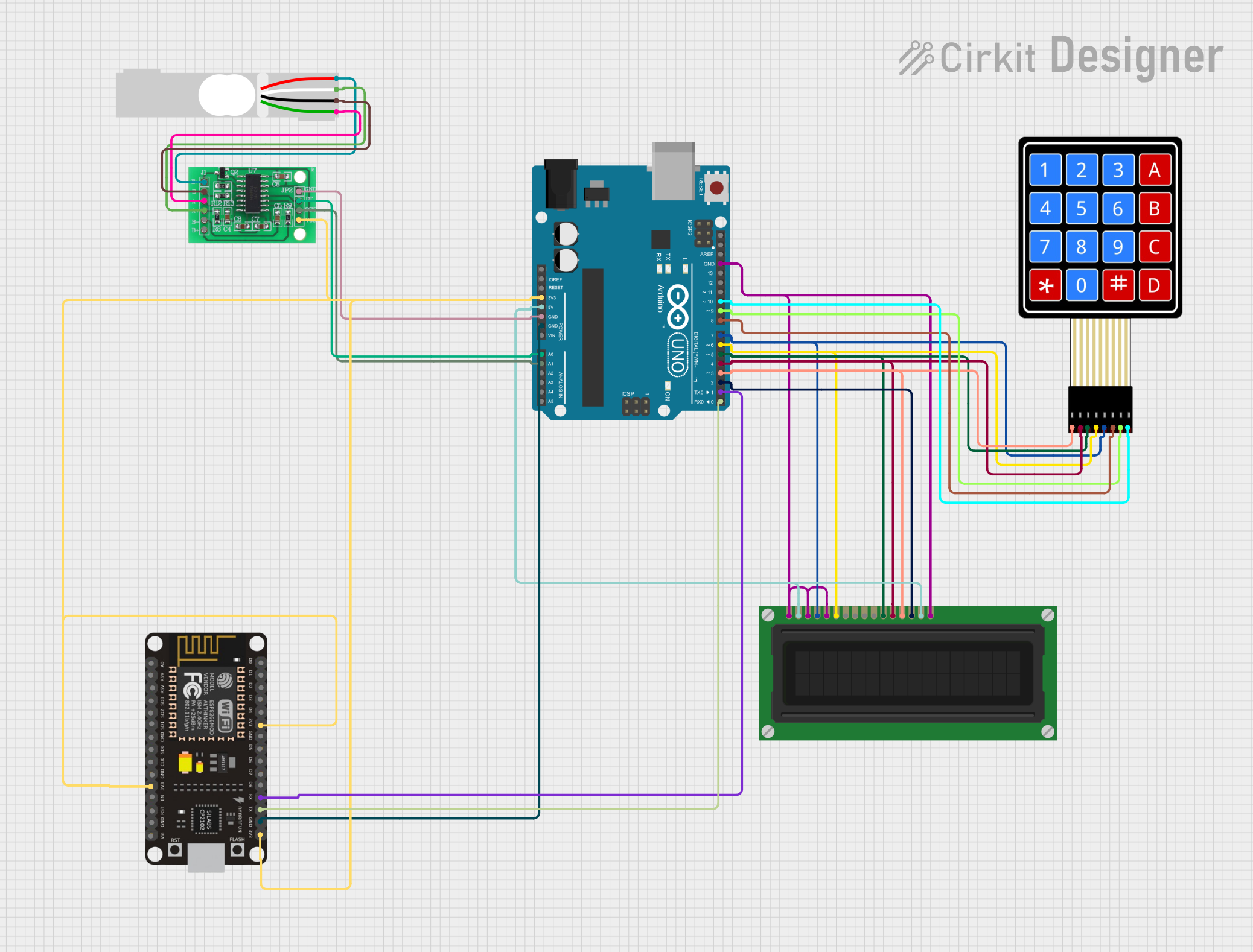
Circuit Documentation
Summary
This circuit is designed to read data from a load cell via the HX711 interface, display the weight on an LCD display, and send the data via WiFi using the ESP8266 module when the star button on the keypad is pressed. The circuit includes an Arduino UNO, an HX711 load cell amplifier, a load cell, a 16x2 LCD display, a 4x4 membrane keypad, and an ESP8266 WiFi module.
Component List
Load Cell - Red/white/black/green
- Description: A sensor used to measure weight.
- Pins: E+, A-, E-, A+
HX711 - Bridge Sensor Interface
- Description: An amplifier and ADC for load cells.
- Pins: E+, E-, A-, A+, B-, B+, GND - GROUND, DATA (OUT), SCK - CLOCK (IN), 3.3/3.5V Supply
LCD Display (16 pin)
- Description: A 16x2 character LCD display.
- Pins: VSS, VDD, VO, RS, R_W, E, DB0, DB1, DB2, DB3, DB4, DB5, DB6, DB7, A, K
4X4 Membrane Matrix Keypad
- Description: A keypad with 4 rows and 4 columns.
- Pins: R1, R2, R3, R4, C1, C2, C3, C4
Arduino UNO
- Description: A microcontroller board based on the ATmega328P.
- Pins: UNUSED, IOREF, Reset, 3.3V, 5V, GND, Vin, A0, A1, A2, A3, A4, A5, SCL, SDA, AREF, D13, D12, D11, D10, D9, D8, D7, D6, D5, D4, D3, D2, D1, D0
esp8266 nodemcu
- Description: A WiFi module with a microcontroller.
- Pins: D0, D1, D2, D3, D4, 3V3, GND, D5, D6, D7, D8, RX, TX, A0, RSV, SD3, SD2, SD1, CMD, SD0, CLK, EN, RST, VIN
Wiring Details
Load Cell - Red/white/black/green
- E+ connected to E+ of HX711
- A- connected to A+ of HX711
- E- connected to E- of HX711
- A+ connected to A- of HX711
HX711 - Bridge Sensor Interface
- E+ connected to E+ of Load Cell
- A- connected to A+ of Load Cell
- E- connected to E- of Load Cell
- A+ connected to A- of Load Cell
- GND - GROUND connected to GND of Arduino UNO
- DATA (OUT) connected to A0 of Arduino UNO
- SCK - CLOCK (IN) connected to A1 of Arduino UNO
- 3.3/3.5V Supply connected to 3.3V of Arduino UNO
LCD Display (16 pin)
- VSS connected to GND of Arduino UNO
- VDD connected to 5V of Arduino UNO
- VO connected to GND of Arduino UNO
- RS connected to D7 of Arduino UNO
- R_W connected to GND of Arduino UNO
- E connected to D6 of Arduino UNO
- DB4 connected to D5 of Arduino UNO
- DB5 connected to D4 of Arduino UNO
- DB6 connected to D3 of Arduino UNO
- DB7 connected to D2 of Arduino UNO
- A connected to 5V of Arduino UNO
- K connected to GND of Arduino UNO
4X4 Membrane Matrix Keypad
- R1 connected to D3 of Arduino UNO
- R2 connected to D4 of Arduino UNO
- R3 connected to D5 of Arduino UNO
- R4 connected to D6 of Arduino UNO
- C1 connected to D7 of Arduino UNO
- C2 connected to D8 of Arduino UNO
- C3 connected to D9 of Arduino UNO
- C4 connected to D10 of Arduino UNO
Arduino UNO
- 3.3V connected to 3.3/3.5V Supply of HX711 and 3V3 of esp8266 nodemcu
- 5V connected to VDD and A of LCD Display
- GND connected to GND - GROUND of HX711, GND of esp8266 nodemcu, VSS, K, VO, and R_W of LCD Display
- A0 connected to DATA (OUT) of HX711
- A1 connected to SCK - CLOCK (IN) of HX711
- D0 connected to TX of esp8266 nodemcu
- D1 connected to RX of esp8266 nodemcu
- D2 connected to DB7 of LCD Display
- D3 connected to DB6 of LCD Display and R1 of Keypad
- D4 connected to DB5 of LCD Display and R2 of Keypad
- D5 connected to DB4 of LCD Display and R3 of Keypad
- D6 connected to E of LCD Display and R4 of Keypad
- D7 connected to RS of LCD Display and C1 of Keypad
- D8 connected to C2 of Keypad
- D9 connected to C3 of Keypad
- D10 connected to C4 of Keypad
esp8266 nodemcu
- 3V3 connected to 3.3V of Arduino UNO
- GND connected to GND of Arduino UNO
- RX connected to D1 of Arduino UNO
- TX connected to D0 of Arduino UNO
Code Documentation
/*
 * This Arduino sketch reads data from a load cell via the HX711 interface,
 * displays the weight on an LCD display, and sends the data via WiFi using
 * the ESP8266 module when the star button on the keypad is pressed. The
 * circuit includes an Arduino UNO, an HX711 load cell amplifier, a load cell,
 * a 16x2 LCD display, a 4x4 membrane keypad, and an ESP8266 WiFi module.
 */

#include <LiquidCrystal.h>
#include <HX711.h>
#include <Keypad.h>
#include <SoftwareSerial.h>

// Pin definitions
const int LOADCELL_DOUT_PIN = A0;
const int LOADCELL_SCK_PIN = A1;
const int LCD_RS = 7;
const int LCD_E = 6;
const int LCD_D4 = 5;
const int LCD_D5 = 4;
const int LCD_D6 = 3;
const int LCD_D7 = 2;
const int KEYPAD_STAR_PIN = 10;
const int ESP8266_RX = 1;
const int ESP8266_TX = 0;

// Initialize the LCD library with the numbers of the interface pins
LiquidCrystal lcd(LCD_RS, LCD_E, LCD_D4, LCD_D5, LCD_D6, LCD_D7);

// Initialize the HX711 library
HX711 scale;

// Initialize the Keypad
const byte ROWS = 4; // Four rows
const byte COLS = 4; // Four columns
char keys[ROWS][COLS] = {
  {'1','2','3','A'},
  {'4','5','6','B'},
  {'7','8','9','C'},
  {'*','0','#','D'}
};
byte rowPins[ROWS] = {9, 8, 7, 6}; // Connect to the row pinouts of the keypad
byte colPins[COLS] = {5, 4, 3, 2}; // Connect to the column pinouts of the keypad
Keypad keypad = Keypad(makeKeymap(keys), rowPins, colPins, ROWS, COLS);

// Initialize SoftwareSerial for ESP8266
SoftwareSerial esp8266(ESP8266_RX, ESP8266_TX);

void setup() {
  // Set up the LCD's number of columns and rows