Cirkit Designer
Your all-in-one circuit design IDE
Home /
Project Documentation
Arduino UNO-Based Ultrasonic Distance Measurement System with GSM and LCD Display
Circuit Documentation
Summary
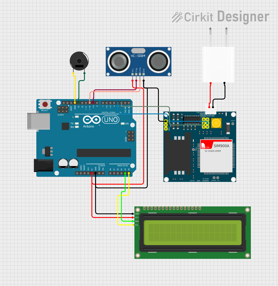
This document provides a detailed overview of a circuit that includes an Arduino UNO microcontroller, an HC-SR04 Ultrasonic Sensor, a Piezo Buzzer, a SIM900A GSM module, a 16x2 I2C LCD, and a 5V Adapter. The circuit is designed to interface these components for various functionalities, including distance measurement, sound output, GSM communication, and display output.
Component List
Arduino UNO
- Description: A microcontroller board based on the ATmega328P.
- Pins: UNUSED, IOREF, Reset, 3.3V, 5V, GND, Vin, A0, A1, A2, A3, A4, A5, SCL, SDA, AREF, D13, D12, D11, D10, D9, D8, D7, D6, D5, D4, D3, D2, D1, D0
HC-SR04 Ultrasonic Sensor
- Description: A sensor used for measuring distance using ultrasonic waves.
- Pins: VCC, TRIG, ECHO, GND
Piezo Buzzer
- Description: A device that produces sound when an electric signal is applied.
- Pins: pin 1, pin 2
SIM900A
- Description: A GSM module used for communication over the GSM network.
- Pins: GND, DB9-3 (RXD), DB9-2 (TXD), 5V, 3VR, 5VR, 3VT, 5VT, VCC, Ring, RESTART, RESET, STATUS
16x2 I2C LCD
- Description: A 16x2 character LCD display with I2C interface.
- Pins: GND, VCC, SDA, SCL
5V Adapter
- Description: A power adapter that provides a 5V output.
- Pins: AC In 1, AC In 2, 5V, GND
Wiring Details
Arduino UNO
- 5V connected to VCC of 16x2 I2C LCD and HC-SR04 Ultrasonic Sensor
- GND connected to GND of 16x2 I2C LCD, HC-SR04 Ultrasonic Sensor, and pin 1 of Piezo Buzzer
- A4 connected to SDA of 16x2 I2C LCD
- A5 connected to SCL of 16x2 I2C LCD
- D13 connected to pin 2 of Piezo Buzzer
- D10 connected to ECHO of HC-SR04 Ultrasonic Sensor
- D9 connected to TRIG of HC-SR04 Ultrasonic Sensor
- D3 connected to 5VR of SIM900A
- D2 connected to 5VT of SIM900A
HC-SR04 Ultrasonic Sensor
- VCC connected to 5V of Arduino UNO
- GND connected to GND of Arduino UNO
- ECHO connected to D10 of Arduino UNO
- TRIG connected to D9 of Arduino UNO
Piezo Buzzer
- pin 1 connected to GND of Arduino UNO
- pin 2 connected to D13 of Arduino UNO
SIM900A
- GND connected to GND of 5V Adapter
- 5V connected to 5V of 5V Adapter
- 5VR connected to D3 of Arduino UNO
- 5VT connected to D2 of Arduino UNO
16x2 I2C LCD
- VCC connected to 5V of Arduino UNO
- GND connected to GND of Arduino UNO
- SDA connected to A4 of Arduino UNO
- SCL connected to A5 of Arduino UNO
5V Adapter
- GND connected to GND of SIM900A
- 5V connected to 5V of SIM900A
Documented Code
Arduino UNO Code (sketch.ino)
void setup() {
  // put your setup code here, to run once:

}

void loop() {
  // put your main code here, to run repeatedly:

}
Additional Documentation (documentation.txt)
This document provides a comprehensive overview of the circuit, including the components used, their wiring details, and the code for the Arduino UNO microcontroller.