
Circuit Documentation
Summary
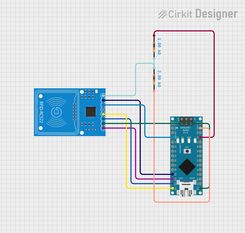
This circuit integrates an RFID-RC522 module with an Arduino Nano to enable RFID reading capabilities. The RFID-RC522 is connected to the Arduino Nano through SPI (Serial Peripheral Interface) for communication, and a couple of resistors are used to create a voltage divider that likely serves to step down the voltage from the Arduino's 5V output to a lower voltage suitable for the RFID-RC522 module, which operates at 3.3V.
Component List
RFID-RC522
- Description: RFID reader/writer module.
- Pins: SDA, SCK, MOSI, MISO, IRQ, GND, RST, 3.3V.
Arduino Nano
- Description: A small, complete, and breadboard-friendly board based on the ATmega328 (Arduino Nano 3.x).
- Pins: D1/TX, D0/RX, RESET, GND, D2, D3, D4, D5, D6, D7, D8, D9, D10, D11/MOSI, D12/MISO, VIN, 5V, A7, A6, A5, A4, A3, A2, A1, A0, AREF, 3V3, D13/SCK.
Resistor (2k Ohms)
- Description: A resistor with a resistance of 2000 Ohms.
- Pins: pin1, pin2.
Resistor (1k Ohms)
- Description: A resistor with a resistance of 1000 Ohms.
- Pins: pin1, pin2.
Wiring Details
RFID-RC522
- SDA connected to Arduino Nano D10.
- SCK connected to Arduino Nano D13/SCK.
- MOSI connected to Arduino Nano D11/MOSI.
- MISO connected to Arduino Nano D12/MISO.
- GND connected to Arduino Nano GND.
- RST connected to Arduino Nano D9.
- 3.3V connected to one end of the 2k Ohms resistor.
Arduino Nano
- D10 connected to RFID-RC522 SDA.
- D13/SCK connected to RFID-RC522 SCK.
- D11/MOSI connected to RFID-RC522 MOSI.
- D12/MISO connected to RFID-RC522 MISO.
- GND connected to RFID-RC522 GND and one end of the 2k Ohms resistor.
- D9 connected to RFID-RC522 RST.
- 5V connected to one end of the 1k Ohms resistor.
Resistor (2k Ohms)
- One end connected to RFID-RC522 3.3V.
- The other end connected to Arduino Nano GND and one end of the 1k Ohms resistor.
Resistor (1k Ohms)
- One end connected to Arduino Nano 5V.
- The other end connected to the 2k Ohms resistor.
Documented Code
#include <MFRC522.h>
#include <MFRC522Extended.h>
#include <deprecated.h>
#include <require_cpp11.h>
#include <SPI.h>
#include <MFRC522.h>

#define RST_PIN         9          // Configurable, see typical pin layout above
#define SS_PIN          10         // Configurable, see typical pin layout above

MFRC522 mfrc522(SS_PIN, RST_PIN);  // Create MFRC522 instance

void setup() {
    Serial.begin(115200);                       // Initialize serial communications with the PC
    while (!Serial);                            // Do nothing if no serial port is opened (added for Arduinos based on ATMEGA32U4)
    SPI.begin();                                // Init SPI bus
    mfrc522.PCD_Init();                         // Init MFRC522
    delay(4);                                   // Optional delay. Some board do need more time after init to be ready, see Readme
    mfrc522.PCD_DumpVersionToSerial();          // Show details of PCD - MFRC522 Card Reader details
    Serial.println(F("Scan PICC to see UID, SAK, type, and data blocks..."));
}

void loop() {
    // Reset the loop if no new card present on the sensor/reader. This saves the entire process when idle.
    if ( ! mfrc522.PICC_IsNewCardPresent()) {
        return;
    }
    // Select one of the cards
    if ( ! mfrc522.PICC_ReadCardSerial()) {
        return;
    }
    // Dump debug info about the card; PICC_HaltA() is automatically called
    mfrc522.PICC_DumpToSerial(&(mfrc522.uid));
}
This code is designed to be uploaded to the Arduino Nano. It initializes the RFID-RC522 module and sets up serial communication. In the loop, it checks for the presence of a new RFID card and reads its data if present, then dumps the card information to the serial output.