
Arduino UNO Based Weather Monitoring System with Rain Sensor and DHT11
View and Edit Project In Cirkit Designer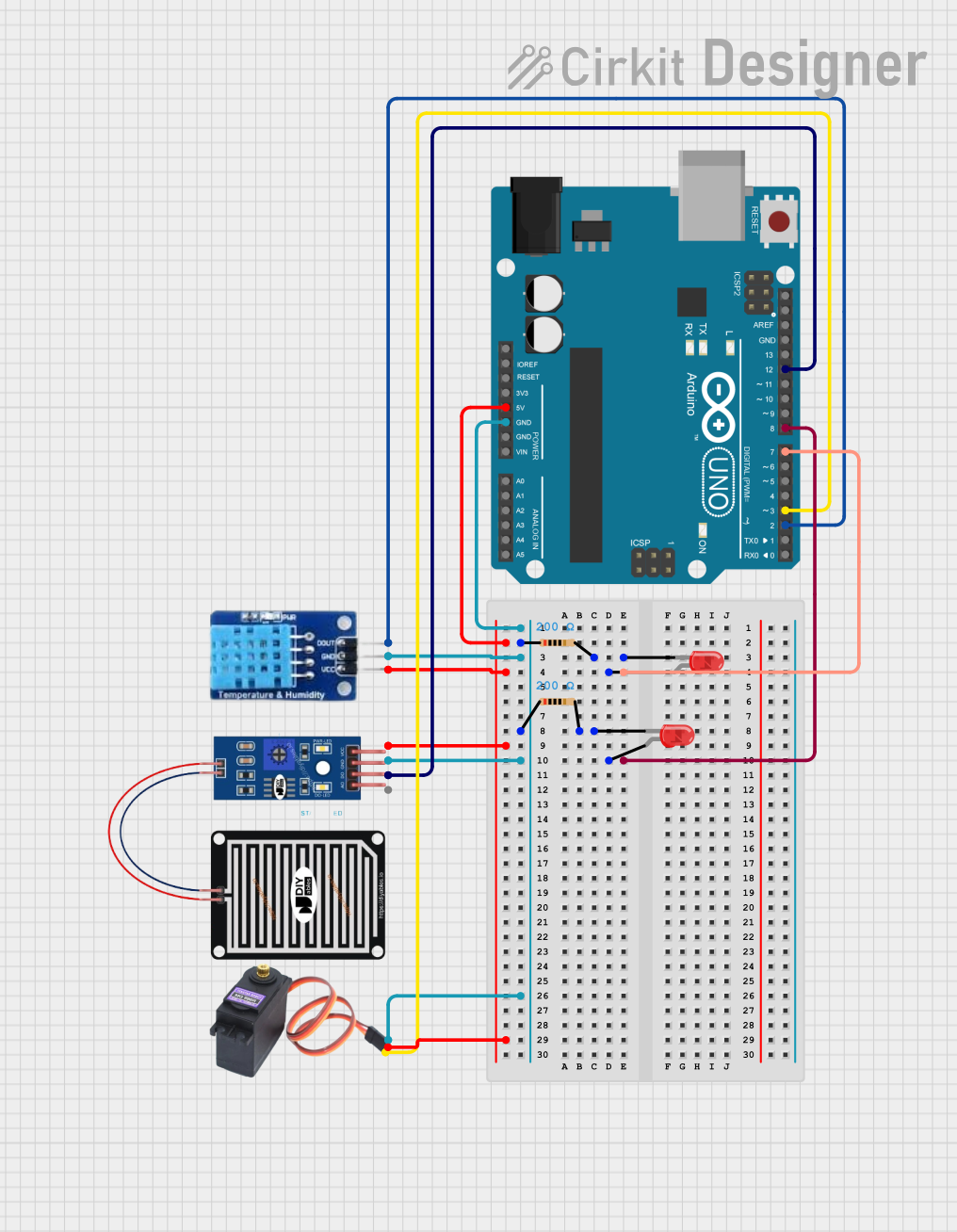
Circuit Documentation
Summary of the Circuit
This circuit is designed to interface with various sensors and actuators using an Arduino UNO microcontroller. It includes a rain sensor and a DHT11 temperature and humidity sensor for environmental data collection. The circuit also controls two red LEDs and a servo motor (MG996R). The LEDs are connected through resistors to limit the current, and the servo motor is controlled via a signal pin. The Arduino UNO provides the necessary logic and power distribution for the sensors, LEDs, and servo motor.
Component List
RAIN SENSOR
- Pins: AO (Analog Output), DO (Digital Output), GRD (Ground), VCC (Power)
- Description: A sensor that detects raindrops by measuring the resistance between two pads.
DHT11
- Pins: DATA, GND (Ground), VCC (Power)
- Description: A sensor that measures ambient temperature and humidity.
Arduino UNO
- Pins: Various digital and analog I/O, power, and ground pins.
- Description: A microcontroller board based on the ATmega328P, with digital and analog inputs/outputs, and onboard voltage regulation.
LED: Two Pin (red)
- Pins: cathode (negative), anode (positive)
- Description: A red light-emitting diode that emits light when powered.
MG996R
- Pins: GND (Ground), VCC (Power), SIG (Signal)
- Description: A high-torque digital servo motor for precise angular movement.
Resistor
- Pins: pin1, pin2
- Description: A passive two-terminal electrical component that implements electrical resistance as a circuit element.
- Properties: Resistance: 200 Ohms
Wiring Details
RAIN SENSOR
- AO: Not connected
- DO: Connected to Arduino UNO pin D12
- GRD: Connected to common ground
- VCC: Connected to Arduino UNO pin 5V
DHT11
- DATA: Connected to Arduino UNO pin D2
- GND: Connected to common ground
- VCC: Connected to Arduino UNO pin 5V
Arduino UNO
- D7: Connected to anode of one red LED
- D8: Connected to anode of another red LED
- GND: Common ground for various components
- 5V: Power supply for RAIN SENSOR, DHT11, and MG996R
- D12: Connected to DO of RAIN SENSOR
- D3: Connected to SIG of MG996R
- D2: Connected to DATA of DHT11
LED: Two Pin (red)
- cathode: Connected to one end of a 200 Ohm resistor
- anode: Connected to Arduino UNO pin D7 or D8 (two instances of LEDs)
MG996R
- GND: Connected to common ground
- VCC: Connected to Arduino UNO pin 5V
- SIG: Connected to Arduino UNO pin D3
Resistor
- pin1: Connected to common ground
- pin2: Connected to cathode of a red LED
- Properties: Resistance: 200 Ohms (two instances of resistors)
Documented Code
Arduino UNO Code (sketch.ino)
void setup() {
  // put your setup code here, to run once:

}

void loop() {
  // put your main code here, to run repeatedly:

}
Note: The provided code is a template and does not include specific logic for interacting with the components. The user should add the necessary code to initialize the sensors and actuators, read sensor data, control the LEDs, and drive the servo motor based on the application requirements.