Arduino UNO Controlled LED Matrix Display with Interactive Pushbuttons
Circuit Documentation
Summary
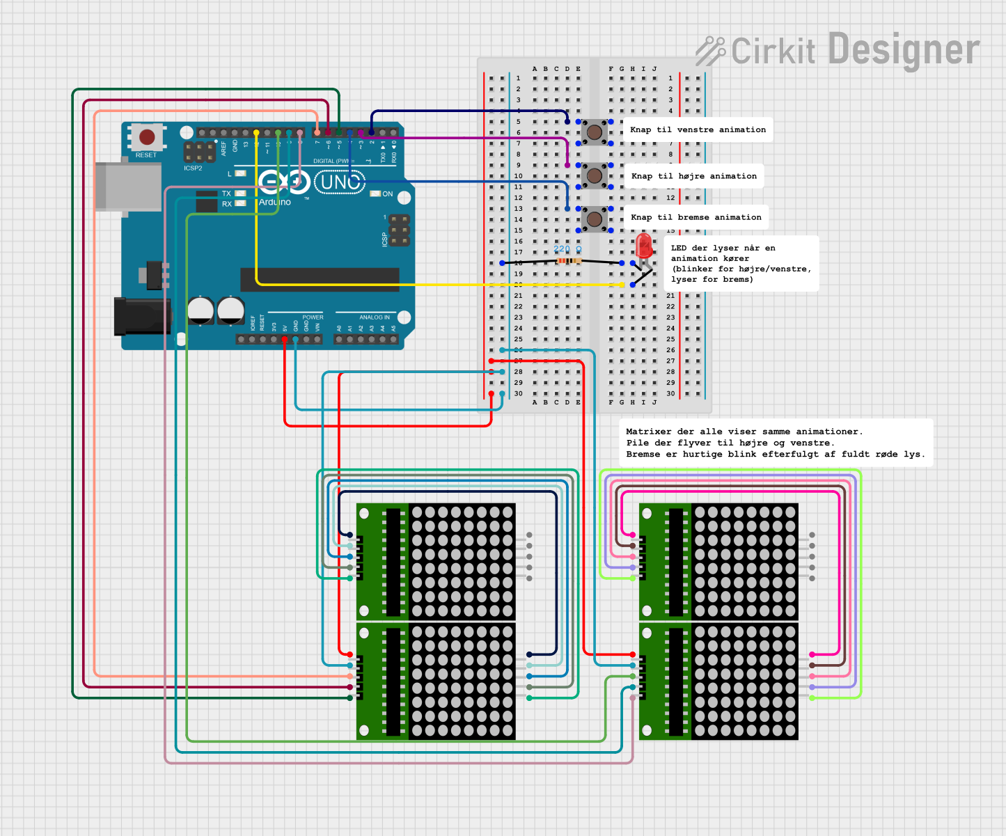
This document provides a detailed overview of a circuit that primarily consists of an Arduino UNO microcontroller interfaced with multiple 8x8 LED matrix modules and pushbuttons. The circuit also includes a red LED with a current-limiting resistor. The Arduino UNO is responsible for controlling the LED matrices and reading the state of the pushbuttons. The red LED serves as an indicator and is connected through a resistor to ensure proper current flow.
Component List
Arduino UNO
- Microcontroller board based on the ATmega328P
- It has 14 digital input/output pins, 6 analog inputs, a 16 MHz quartz crystal, a USB connection, a power jack, an ICSP header, and a reset button.
8x8 LED Matrix (x4)
- Each matrix has an array of 64 LEDs arranged in an 8x8 grid.
- They have pins for power (Vcc and Gnd), data input (DIN), clock (CLK), and chip select (CS).
Pushbutton (x3)
- A simple switch mechanism for controlling some aspect of a machine or a process.
- It has four pins: two for the input and two for the output.
Resistor
- A passive two-terminal electrical component that implements electrical resistance as a circuit element.
- Resistance: 220 Ohms
LED: Two Pin (red)
- A red light-emitting diode that emits red light when a voltage is applied across its terminals.
- It has two pins: anode and cathode.
Wiring Details
Arduino UNO
- Digital Pin 2 connected to Pushbutton 1
- Digital Pin 3 connected to Pushbutton 2
- Digital Pin 4 connected to Pushbutton 3
- Digital Pin 5 connected to 8x8 Matrix 1 CS
- Digital Pin 6 connected to 8x8 Matrix 1 CLK
- Digital Pin 7 connected to 8x8 Matrix 1 DIN
- Digital Pin 8 connected to 8x8 Matrix 2 CS
- Digital Pin 9 connected to 8x8 Matrix 2 CLK
- Digital Pin 10 connected to 8x8 Matrix 2 DIN
- Digital Pin 12 connected to the anode of the red LED
- 5V pin connected to the Vcc of all 8x8 Matrix modules
- GND pin connected to the Gnd of all 8x8 Matrix modules and one terminal of the resistor
8x8 LED Matrix
- Vcc connected to Arduino UNO 5V
- Gnd connected to Arduino UNO GND (through a resistor for one matrix)
- DIN connected to Arduino UNO Digital Pins (D7, D10)
- CLK connected to Arduino UNO Digital Pins (D6, D9)
- CS connected to Arduino UNO Digital Pins (D5, D8)
Pushbutton
- One output pin connected to Arduino UNO Digital Pins (D2, D3, D4)
Resistor
- One terminal connected to the Gnd of an 8x8 Matrix
- The other terminal connected to the cathode of the red LED
LED: Two Pin (red)
- Anode connected to Arduino UNO Digital Pin 12
- Cathode connected to one terminal of the resistor
Documented Code
void setup() {
  // put your setup code here, to run once:

}

void loop() {
  // put your main code here, to run repeatedly:

}
The provided code is a template with empty setup() and loop() functions, which are the standard structure for Arduino sketches. The setup() function is intended to contain initialization code that runs once when the microcontroller is powered on or reset. The loop() function is meant to contain the main logic of the program, which runs repeatedly as long as the microcontroller is powered.