
Arduino-Controlled Robotic Vehicle with Bluetooth Interface and Obstacle Avoidance
View and Edit Project In Cirkit Designer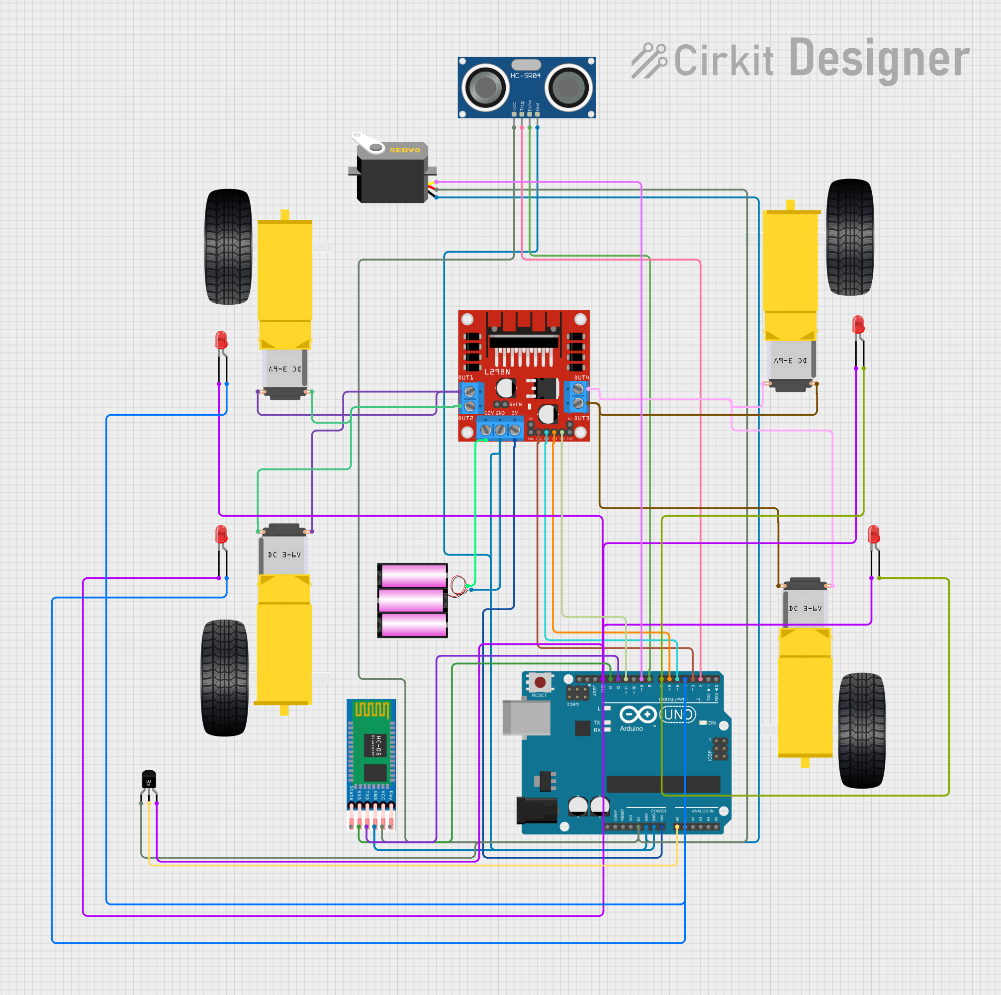
Circuit Documentation
Summary
The circuit in question appears to be designed for a mobile robot or vehicle with wireless control capabilities. It includes motor drivers for wheel movement, an ultrasonic sensor for distance measurement, a Bluetooth module for wireless communication, a temperature sensor, servo motors, LEDs for indication, and a microcontroller (Arduino UNO) to manage the logic and sensor data processing. The circuit is powered by a 12V battery, which also supplies power to the motor driver and through it to the Arduino UNO.
Component List
L298N DC Motor Driver
- Description: A motor driver module capable of driving two DC motors or one stepper motor.
- Pins: OUT1, OUT2, 12V, GND, 5V, OUT3, OUT4, ENA, IN1, IN2, IN3, IN4, ENB.
Arduino UNO
- Description: A microcontroller board based on the ATmega328P, widely used for building digital devices and interactive objects.
- Pins: IOREF, Reset, 3.3V, 5V, GND, Vin, A0-A5, SCL, SDA, AREF, D0-D13.
HC-05 Bluetooth Module
- Description: A Bluetooth module for wireless communication.
- Pins: EN, VCC, GND, TXD, RXD, STATE.
HC-SR04 Ultrasonic Sensor
- Description: An ultrasonic sensor used for measuring distances via ultrasonic waves.
- Pins: VCC, TRIG, ECHO, GND.
Gearmotor DC Wheels (Left and Right)
- Description: DC motors with gear reduction used for driving the wheels of a robot or vehicle.
- Pins: PIN1, PIN2.
Temperature Sensor (LM35)
- Description: An analog temperature sensor with a linear voltage output proportional to the temperature.
- Pins: +Vs, Vout, GND.
Servo
- Description: A rotary actuator or linear actuator that allows for precise control of angular or linear position.
- Pins: GND, VCC, PULSE.
12V Battery
- Description: A power source for the circuit.
- Pins: +, -.
LED: Two Pin (Red)
- Description: A basic red LED for indication purposes.
- Pins: Cathode, Anode.
Wiring Details
L298N DC Motor Driver
- OUT1, OUT2 connected to left gearmotor wheels.
- OUT3, OUT4 connected to right gearmotor wheels.
- 12V connected to the 12V battery positive terminal.
- GND connected to the 12V battery negative terminal and shared with other components.
- 5V output used to power the Arduino UNO Vin pin.
- IN1, IN2, IN3, IN4 connected to Arduino UNO digital pins D3, D5, D6, D11 respectively.
Arduino UNO
- Vin connected to L298N 5V output.
- GND connected to the 12V battery negative terminal and shared with other components.
- 5V output used to power HC-05, HC-SR04, Servo, and LM35.
- A0 connected to LM35 Vout.
- D2, D8, D9, D12, D13 connected to HC-SR04 TRIG, ECHO, Servo PULSE, HC-05 TXD, RXD respectively.
- D3, D5, D6, D11 connected to L298N IN1, IN2, IN3, IN4 respectively.
- D4, D7 connected to LED anodes.
HC-05 Bluetooth Module
- VCC connected to Arduino 5V.
- GND connected to the 12V battery negative terminal.
- TXD, RXD connected to Arduino UNO digital pins D12, D13 respectively.
HC-SR04 Ultrasonic Sensor
- VCC connected to Arduino 5V.
- TRIG, ECHO connected to Arduino UNO digital pins D2, D8 respectively.
- GND connected to the 12V battery negative terminal.
Gearmotor DC Wheels (Left and Right)
- PIN1, PIN2 connected to L298N OUT1, OUT2 for left wheels and OUT3, OUT4 for right wheels.
Temperature Sensor (LM35)
- +Vs connected to Arduino 5V.
- Vout connected to Arduino UNO analog pin A0.
- GND connected to the 12V battery negative terminal.
Servo
- VCC connected to Arduino 5V.
- PULSE connected to Arduino UNO digital pin D9.
- GND connected to the 12V battery negative terminal.
12V Battery
-
- connected to L298N 12V.
-
- connected to the 12V battery negative terminal and shared with other components.
LED: Two Pin (Red)
- Cathodes connected to the 12V battery negative terminal.
- Anodes connected to Arduino UNO digital pins D4, D7.
Documented Code
#define CUSTOM_SETTINGS
#define INCLUDE_GAMEPAD_MODULE
#define INCLUDE_DASHBOARD_MODULE // Include Dashboard module
#include <Dabble.h>

const unsigned int trig = 2;
const unsigned int echo = 8;

// Right motor
int rightMotorPin1 = 3;
int rightMotorPin2 = 5;
int sensorPin = A0; // Temperature sensor pin, if needed

// Left motor
int leftMotorPin1 = 6;
int leftMotorPin2 = 9;

void setup() {
    pinMode(rightMotorPin1, OUTPUT);
    pinMode(rightMotorPin2, OUTPUT);
    pinMode(leftMotorPin1, OUTPUT);
    pinMode(leftMotorPin2, OUTPUT);
    pinMode(trig, OUTPUT);
    pinMode(echo, INPUT);

    rotateMotor(0, 0);
    Dabble.begin(9600, 10, 11);
    Serial.begin(9600);
}

void loop() {
    unsigned long duration; // Variable for measuring time
    int distance;           // Variable for storing distance

    // Generate pulse from trig pin
    digitalWrite(trig, LOW);   // Turn off trig
    delayMicroseconds(2);
    digitalWrite(trig, HIGH);  // Generate pulse from trig
    delayMicroseconds(5);      // Pulse duration is 5 microseconds
    digitalWrite(trig, LOW);   // Turn off trig

    // Calculate the duration
    duration = pulseIn(echo, HIGH);
    distance = int(duration / 2 / 29.412); // Calculate distance (cm)

    Serial.println(distance); // Print distance to Serial Monitor

    int rightMotorSpeed = 0;
    int leftMotorSpeed = 0;

    Dabble.processInput();

    // Check distance
    if (distance <= 15) { // If distance is less than 15 cm
        rightMotorSpeed = -100; // Move backward
        leftMotorSpeed = -100;
    } else {
        // Control using GamePad
        if (GamePad.isUpPressed()) {
            rightMotorSpeed = 100;
            leftMotorSpeed = 100;
        } else if (GamePad.isDownPressed()) {
            rightMotorSpeed = -100;
            leftMotorSpeed = -100;
        } else if (GamePad.isLeftPressed()) {
            rightMotorSpeed = 100;
            leftMotorSpeed = 0;
        } else if (GamePad.isRightPressed()) {
            rightMotorSpeed = 0;
            leftMotorSpeed = 100;
        } else {
            rightMotorSpeed = 0;
            leftMotorSpeed = 0; // Stop
        }
    }

    // Function to control motors
    rotateMotor(rightMotorSpeed, leftMotorSpeed);
}

void rotateMotor(int rightMotorSpeed, int leftMotorSpeed) {
    // Control right motor
    if (rightMotorSpeed < 0) {
        analogWrite(rightMotorPin1, 0);
        analogWrite(rightMotorPin2, 100);
    } else if (rightMotorSpeed > 0) {
        analogWrite(rightMotorPin1, 100);
        analogWrite(rightMotorPin2, 0);
    } else {
        analogWrite(rightMotorPin1, 0);
        analogWrite(rightMotorPin2, 0);
    }

    // Control left motor
    if (leftMotorSpeed < 0) {
        analogWrite(leftMotorPin1, 0);
        analogWrite(leftMotorPin2, 100);
    } else if (leftMotorSpeed > 0) {
        analogWrite(leftMotorPin1, 100);
        analogWrite(leftMotorPin2, 0);
    } else {
        analogWrite(leftMotorPin1, 0);
        analogWrite(leftMotorPin2, 0);
    }
}
This code is designed to control a robot's movement using an Arduino UNO, with inputs from an ultrasonic sensor and a Bluetooth module. The robot can move forward, backward, and turn based on the distance detected by the ultrasonic sensor or commands received via Bluetooth. The temperature sensor's data is read but not used in the control logic. The LEDs are controlled directly by the Arduino's digital pins and are likely used as status indicators.