Cirkit Designer
Your all-in-one circuit design IDE
Home /
Project Documentation
Arduino-Controlled Line Follower and Obstacle Avoiding Robot with IR and Ultrasonic Sensors
Circuit Documentation
Summary
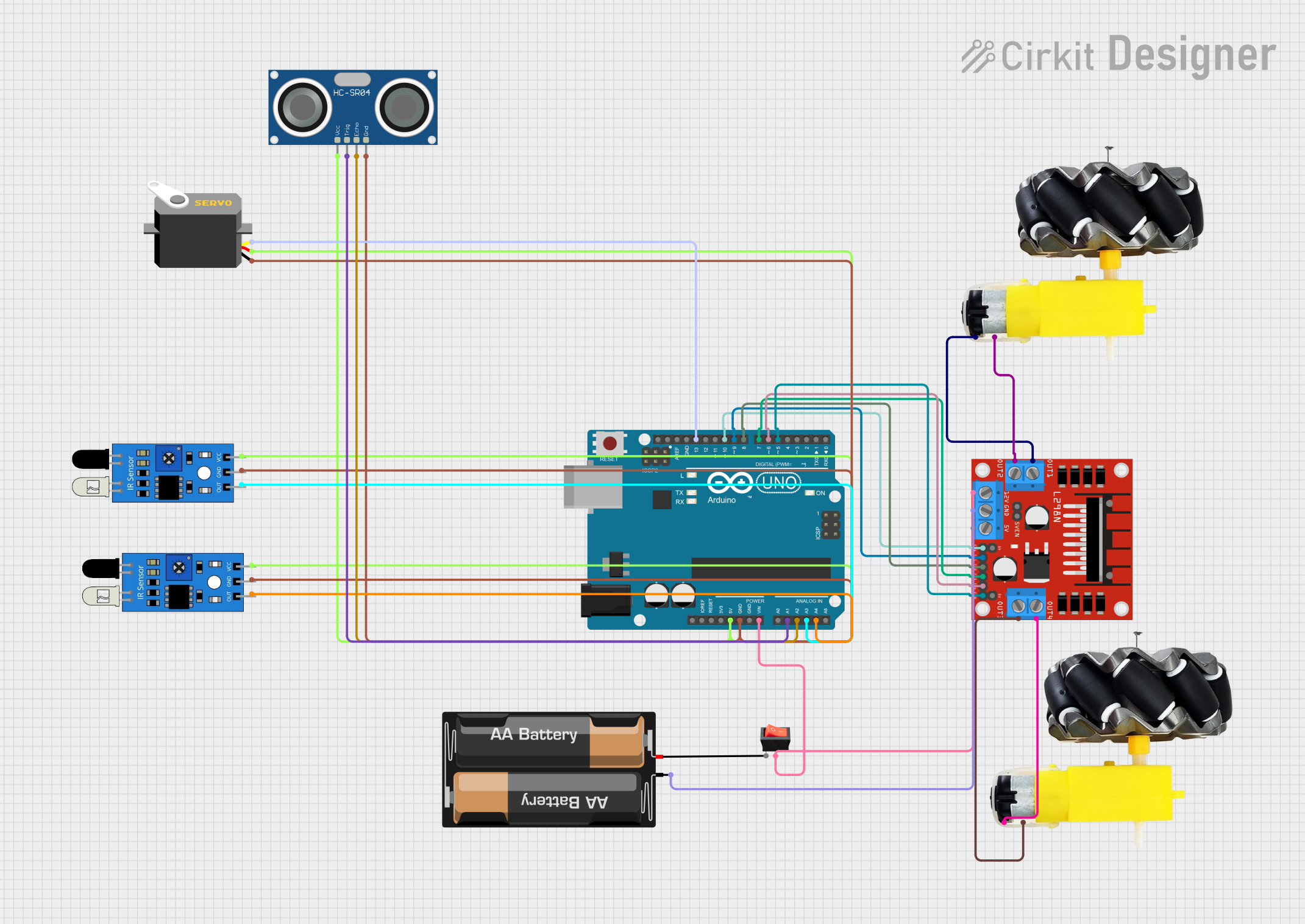
This circuit is designed to control a robotic vehicle with two DC motors, an ultrasonic sensor for distance measurement, two IR sensors for line following, and a servo motor for directional control. The brain of the vehicle is an Arduino UNO microcontroller, which interfaces with an L298N DC motor driver to control the motors' speed and direction. The ultrasonic sensor is used to detect obstacles, while the IR sensors are used to follow a line or path. A rocker switch is included to control the power supply to the circuit. The power is provided by a 2 x AA battery mount.
Component List
L298N DC Motor Driver
- Description: A module used for controlling up to two DC motors with a maximum current of 2A per channel.
- Pins: OUT1, OUT2, 12V, GND, 5V, OUT3, OUT4, ENA, IN1, IN2, IN3, IN4, ENB
Motor and Wheels (x2)
- Description: DC motors connected to wheels, providing the motion for the robotic vehicle.
- Pins: vcc, GND
Arduino UNO
- Description: A microcontroller board based on the ATmega328P, used for controlling the various components of the circuit.
- Pins: Vin, GND, 5V, A0-A5, D0-D13
2 x AA Battery Mount
- Description: A battery holder for two AA batteries, providing power to the circuit.
- Pins: +, -
Rocker Switch
- Description: A switch used to control the power supply to the circuit.
- Pins: output, input
IR Sensor (x2)
- Description: Infrared sensors used for line following or obstacle detection.
- Pins: out, gnd, vcc
Servo
- Description: A small motor capable of precise position control.
- Pins: gnd, vcc, pulse
HC-SR04 Ultrasonic Sensor
- Description: A sensor used for measuring distances via ultrasonic sound waves.
- Pins: VCC, TRIG, ECHO, GND
Wiring Details
L298N DC Motor Driver
- OUT1 connected to Motor and Wheels (Motor 1 vcc)
- OUT2 connected to Motor and Wheels (Motor 1 GND)
- 12V connected to Arduino UNO (Vin) and Rocker Switch (output)
- GND connected to 2 x AA Battery Mount (-)
- OUT3 connected to Motor and Wheels (Motor 2 GND)
- OUT4 connected to Motor and Wheels (Motor 2 vcc)
- ENA connected to Arduino UNO (D10)
- IN1 connected to Arduino UNO (D9)
- IN2 connected to Arduino UNO (D8)
- IN3 connected to Arduino UNO (D7)
- IN4 connected to Arduino UNO (D6)
- ENB connected to Arduino UNO (D5)
Motor and Wheels
- Two instances, each connected to the L298N DC Motor Driver (OUT1/OUT2 for Motor 1, OUT3/OUT4 for Motor 2)
Arduino UNO
- Vin connected to L298N DC Motor Driver (12V)
- GND connected to all GND pins of IR Sensors, Servo, and HC-SR04 Ultrasonic Sensor
- 5V connected to all vcc pins of IR Sensors, Servo, and HC-SR04 Ultrasonic Sensor
- A1 connected to HC-SR04 Ultrasonic Sensor (TRIG)
- A2 connected to HC-SR04 Ultrasonic Sensor (ECHO)
- A3 connected to IR Sensor (out)
- A4 connected to IR Sensor (out)
- D5-D13 connected to L298N DC Motor Driver and Servo as per the code
2 x AA Battery Mount
- connected to L298N DC Motor Driver (12V through Rocker Switch)
- connected to L298N DC Motor Driver (GND)
Rocker Switch
- Output connected to L298N DC Motor Driver (12V)
- Input connected to 2 x AA Battery Mount (+)
IR Sensors
- vcc connected to Arduino UNO (5V)
- gnd connected to Arduino UNO (GND)
- out connected to Arduino UNO (A3, A4)
Servo
- vcc connected to Arduino UNO (5V)
- gnd connected to Arduino UNO (GND)
- pulse connected to Arduino UNO (D13)
HC-SR04 Ultrasonic Sensor
- VCC connected to Arduino UNO (5V)
- TRIG connected to Arduino UNO (A1)
- ECHO connected to Arduino UNO (A2)
- GND connected to Arduino UNO (GND)
Documented Code
// Define L298N Motor Driver pins
#define enA 5
#define in1 7
#define in2 8
#define in3 9
#define in4 10
#define enB 6

// Define IR sensor pins
#define L_S A3 // Left IR sensor
#define R_S A4 // Right IR sensor

// Define Ultrasonic sensor pins
#define echo A2    // Echo pin
#define trigger A1 // Trigger pin

// Define Servo pin
#define servo 13

// Set distance for obstacle avoidance
int Set = 10;
int distance_L, distance_F, distance_R;

void setup() {
  Serial.begin(9600); // Start serial communication at 9600bps

  // Initialize IR sensors as inputs
  pinMode(R_S, INPUT);
  pinMode(L_S, INPUT);

  // Initialize Ultrasonic sensor pins
  pinMode(echo, INPUT);
  pinMode(trigger, OUTPUT);

  // Initialize L298N Motor Driver pins
  pinMode(enA, OUTPUT);
  pinMode(in1, OUTPUT);
  pinMode(in2, OUTPUT);
  pinMode(in3, OUTPUT);
  pinMode(in4, OUTPUT);
  pinMode(enB, OUTPUT);

  // Set initial motor speed
  analogWrite(enA, 120);
  analogWrite(enB, 120);

  // Initialize Servo pin
  pinMode(servo, OUTPUT);

  // Sweep servo to check surroundings
  sweepServo();

  // Read distance from Ultrasonic sensor
  distance_F = Ultrasonic_read();

  delay(500);
}

void loop() {
  // Read distance from Ultrasonic sensor
  distance_F = Ultrasonic_read();
  Serial.print("D F="); Serial.println(distance_F);

  // Line following and obstacle avoiding logic
  if ((digitalRead(R_S) == 1) && (digitalRead(L_S) == 1)) {
    if (distance_F > Set) { forword(); }
    else { Check_side(); }
  }
  else if ((digitalRead(R_S) == 1) && (digitalRead(L_S) == 0)) { turnRight(); }
  else if ((digitalRead(R_S) == 0) && (digitalRead(L_S) == 1)) { turnLeft(); }
  else if ((digitalRead(R_S) == 0) && (digitalRead(L_S) == 0)) { Stop(); }

  delay(10);
}

// Function to control servo movement
void servoPulse(int pin, int angle) {
  int pwm = (angle * 11) + 500; // Convert angle to microseconds
  digitalWrite(pin, HIGH);
  delayMicroseconds(pwm);
  digitalWrite(pin, LOW);
  delay(50); // Refresh cycle of servo
}

// Function to read distance from Ultrasonic sensor
long Ultrasonic_read() {
  digitalWrite(trigger, LOW);
  delayMicroseconds(2);
  digitalWrite(trigger, HIGH);
  delayMicroseconds(10);
  long time = pulseIn(echo, HIGH);
  return time / 29 / 2;
}

// Function to compare distances and decide direction
void compareDistance() {
  if (distance_L > distance_R) {
    turnLeft();
    delay(200);
    forword();
    delay(700);
    turnRight();
    delay(500);
  }
  else {
    turnRight();
    delay(300);
    forword();
    delay(700);
    turnLeft();
    delay(500);
  }
}

// Function to check side distances
void Check_side() {
  Stop();
  delay(100);
  sweepServo();
  compareDistance();
}

// Function to move forward
void forword() {
  digitalWrite(in1, LOW);
  digitalWrite(in2, HIGH);
  digitalWrite(in3, HIGH);
  digitalWrite(in4, LOW);
}

// Function to turn right
void turnRight() {
  digitalWrite(in1, LOW);
  digitalWrite(in2, HIGH);
  digitalWrite(in3, LOW);
  digitalWrite(in4, HIGH);
}

// Function to turn left
void turnLeft() {
  digitalWrite(in1, HIGH);
  digitalWrite(in2, LOW);
  digitalWrite(in3, HIGH);
  digitalWrite(in4, LOW);
}

// Function to stop the motors
void Stop() {
  digitalWrite(in1, LOW);
  digitalWrite(in2, LOW);
  digitalWrite(in3, LOW);
  digitalWrite(in4, LOW);
}

// Function to sweep the servo and read distances
void sweepServo() {
  for (int angle = 70; angle <= 140; angle += 5) {
    servoPulse(servo, angle);
  }
  delay(300);
  distance_R = Ultrasonic_read();
  Serial.print("D R