
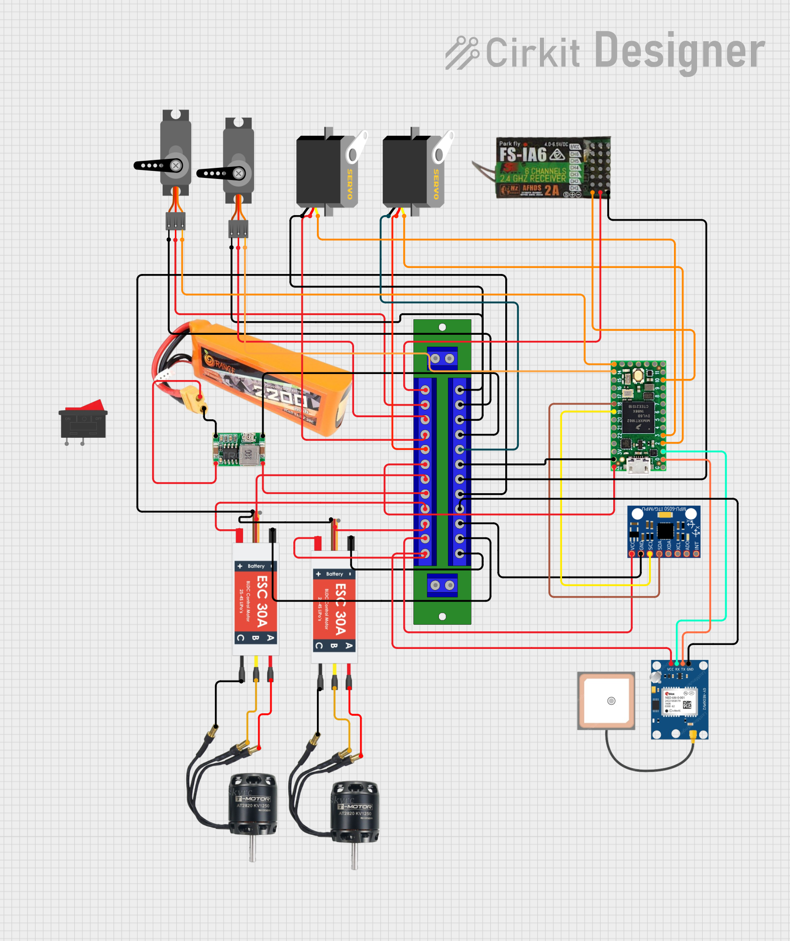
Circuit Documentation
Summary
The circuit in question appears to be designed for a remote-controlled vehicle or drone, featuring brushless DC (BLDC) motors, electronic speed controllers (ESCs), servos for actuation, a GPS module for positioning, an inertial measurement unit (MPU-6050) for motion tracking, and a Teensy 4.0 microcontroller for control logic. Power is supplied by a LiPo battery, regulated by a Mini 360 Buck Converter, and distributed via a Distribution Board. A FLYSKY FS-IA6 receiver is included for remote control functionality.
Component List
BLDC Motor
- Description: A brushless DC motor used for propulsion.
- Pins: Wire A, Wire B, Wire C
Electronic Speed Controller (ESC)
- Description: Controls the speed of the BLDC motor.
- Pins: Battery VCC, Battery GND, Signal, 5v out, GND out, M1, M2, M3
Servo
- Description: An actuator for controlling angular position.
- Pins: GND, VCC, PWM/pulse
Mini 360 Buck Converter
- Description: Steps down voltage from the battery to a lower voltage.
- Pins: IN-, OUT-, OUT+, IN+
Teensy 4.0
- Description: A powerful microcontroller board for controlling the circuit.
- Pins: GND, RX1, TX1, PWM, RX2, TX2, VBat, 3.3v, Program, On/Off, SCX, A0, A1, A2, A3, SCA0, SCL0, A6, A7, A8, A9, Vin
GPS NEO 6M
- Description: Provides positioning data for the vehicle.
- Pins: VCC, RX, TX, GND
Rocker Switch
- Description: A simple on/off switch.
- Pins: 1, 2
LiPo Battery 2200mAh 30C
- Description: Provides power to the circuit.
- Pins: VCC, GND
MPU-6050
- Description: A motion tracking device with a gyroscope and accelerometer.
- Pins: VCC, GND, SCL, SDA, XDA, XCL, AD0, INT
Distribution Board
- Description: Distributes power to various components in the circuit.
- Pins: 12V +, 12V -, 12V +
FLYSKY FS-IA6
- Description: A receiver for remote control signals.
- Pins: CH1, 5V, GND, CH2, CH3, CH4, CH5, CH6, VCC
Wiring Details
BLDC Motor
- Wire A, Wire B, Wire C connected to corresponding M1, M2, M3 pins on the ESC.
Electronic Speed Controller (ESC)
- Battery VCC and Battery GND connected to the Distribution Board.
- M1, M2, M3 connected to the BLDC Motor.
- 5v out and GND out may be used to power other components or for signal reference.
Servo
- GND and VCC connected to the Distribution Board.
- PWM/pulse connected to a PWM-capable pin on the Teensy 4.0 for control.
Mini 360 Buck Converter
- IN+ and IN- connected to the LiPo Battery.
- OUT+ and OUT- connected to the Distribution Board.
Teensy 4.0
- GND and Vin connected to the Distribution Board.
- RX1, TX1 used for communication with the GPS NEO 6M.
- SCA0, SCL0 used for communication with the MPU-6050.
- PWM pins connected to Servos and the FLYSKY FS-IA6 receiver.
GPS NEO 6M
- VCC and GND connected to the Distribution Board.
- RX and TX connected to TX1 and RX1 on the Teensy 4.0 for communication.
LiPo Battery 2200mAh 30C
- VCC and GND connected to the Mini 360 Buck Converter.
MPU-6050
- VCC and GND connected to the Distribution Board.
- SCL and SDA connected to SCL0 and SCA0 on the Teensy 4.0 for communication.
Distribution Board
- Receives power from the Mini 360 Buck Converter and distributes it to the ESCs, Servos, GPS NEO 6M, MPU-6050, Teensy 4.0, and FLYSKY FS-IA6.
FLYSKY FS-IA6
- VCC and GND connected to the Distribution Board.
- CH1 connected to a PWM pin on the Teensy 4.0 for control signal input.
Documented Code
No code was provided in the input. When code is available, it should be documented here with explanations of the functionality, setup, and main loop, along with any interrupt service routines or additional functions. Code comments should explain the purpose of each section and the logic behind it.