
Arduino UNO Autonomous Vehicle with GPS and Compass Navigation
View and Edit Project In Cirkit Designer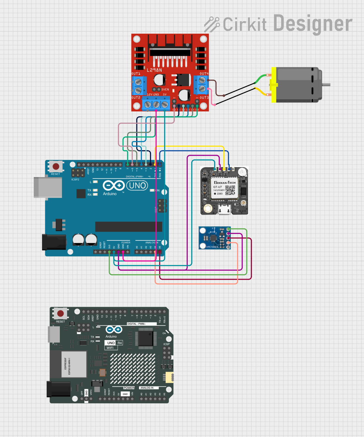
Circuit Documentation
Summary
This circuit is designed for an Auto Drive Project. It controls a DC motor using an L298N motor driver, reads GPS data from a neo 6m GPS module, and reads compass data from an HMC5883L compass module. The Arduino UNO is used to control the motor and read sensor data.
Component List
Arduino UNO
- Description: Microcontroller board based on the ATmega328P.
- Pins: UNUSED, IOREF, Reset, 3.3V, 5V, GND, Vin, A0, A1, A2, A3, A4, A5, SCL, SDA, AREF, D13, D12, D11, D10, D9, D8, D7, D6, D5, D4, D3, D2, D1, D0
Arduino UNO R4 WiFi
- Description: Microcontroller board with WiFi capabilities.
- Pins: OFF, GND, VRTC, IIC0_SCL, IIC0_SDA, 3V3, GPIO 41, GPIO 0, GPIO 42, GPIO 43, GPIO 44, BOOT, IOREF, RESET, 5V, VIN, A0, A1, A2, A3, A4, A5, RSPCKA, CIPO, COPI, D0/RX, D1/TX, D2, D3, D4, D5, D6, D7, D8, D9, D10, D11, D12, D13, AREF, SDA, SCL
neo 6m GPS
- Description: GPS module for receiving location data.
- Pins: VCC, GND, RXD, TXD, PPS
HMC5883L Compass
- Description: Compass module for reading magnetic field data.
- Pins: DRDY, SDA, SCL, GND, VCC
L298N DC Motor Driver
- Description: Dual H-Bridge motor driver for controlling DC motors.
- Pins: OUT1, OUT2, 12V, GND, 5V, OUT3, OUT4, 5V-ENA-JMP-I, 5V-ENA-JMP-O, +5V-J1, +5V-J2, ENA, IN1, IN2, IN3, IN4, ENB
DC Motor
- Description: Standard DC motor.
- Pins: pin 1, pin 2
Wiring Details
Arduino UNO
- 3.3V connected to HMC5883L Compass VCC
- 5V connected to neo 6m GPS VCC and L298N DC Motor Driver 5V
- GND connected to neo 6m GPS GND, HMC5883L Compass GND, and L298N DC Motor Driver GND
- A4 connected to HMC5883L Compass SDA
- A5 connected to HMC5883L Compass SCL
- D7 connected to L298N DC Motor Driver ENB
- D6 connected to L298N DC Motor Driver ENA
- D5 connected to L298N DC Motor Driver IN4
- D4 connected to L298N DC Motor Driver IN3
- D3 connected to L298N DC Motor Driver IN2
- D2 connected to L298N DC Motor Driver IN1
- D1 connected to neo 6m GPS RXD
- D0 connected to neo 6m GPS TXD
Arduino UNO R4 WiFi
- No specific connections detailed in the provided net list.
neo 6m GPS
- VCC connected to Arduino UNO 5V
- GND connected to Arduino UNO GND
- RXD connected to Arduino UNO D1
- TXD connected to Arduino UNO D0
HMC5883L Compass
- VCC connected to Arduino UNO 3.3V
- GND connected to Arduino UNO GND
- SDA connected to Arduino UNO A4
- SCL connected to Arduino UNO A5
L298N DC Motor Driver
- 5V connected to Arduino UNO 5V
- GND connected to Arduino UNO GND
- ENA connected to Arduino UNO D6
- ENB connected to Arduino UNO D7
- IN1 connected to Arduino UNO D2
- IN2 connected to Arduino UNO D3
- IN3 connected to Arduino UNO D4
- IN4 connected to Arduino UNO D5
- OUT3 connected to DC Motor pin 2
- OUT4 connected to DC Motor pin 1
DC Motor
- pin 1 connected to L298N DC Motor Driver OUT4
- pin 2 connected to L298N DC Motor Driver OUT3
Code Documentation
Arduino UNO Code
/*
 * Auto Drive Project
 * This code controls a DC motor using an L298N motor driver, reads GPS data
 * from a neo 6m GPS module, and reads compass data from an HMC5883L compass
 * module. The Arduino UNO is used to control the motor and read sensor data.
 */

#include <Wire.h>
#include <SoftwareSerial.h>

// Pins for L298N motor driver
const int IN1 = 2;
const int IN2 = 3;
const int IN3 = 4;
const int IN4 = 5;
const int ENA = 6;
const int ENB = 7;

// GPS module pins
const int GPS_RX = 0;
const int GPS_TX = 1;

// Compass module I2C address
const int COMPASS_ADDR = 0x1E;

SoftwareSerial gpsSerial(GPS_RX, GPS_TX);

void setup() {
  // Initialize serial communication
  Serial.begin(9600);
  gpsSerial.begin(9600);
  Wire.begin();

  // Initialize motor driver pins
  pinMode(IN1, OUTPUT);
  pinMode(IN2, OUTPUT);
  pinMode(IN3, OUTPUT);
  pinMode(IN4, OUTPUT);
  pinMode(ENA, OUTPUT);
  pinMode(ENB, OUTPUT);

  // Initialize compass
  Wire.beginTransmission(COMPASS_ADDR);
  Wire.write(0x02);
  Wire.write(0x00);
  Wire.endTransmission();
}

void loop() {
  // Read GPS data
  while (gpsSerial.available()) {
    char c = gpsSerial.read();
    Serial.print(c);
  }

  // Read compass data
  int x, y, z;
  Wire.beginTransmission(COMPASS_ADDR);
  Wire.write(0x03);
  Wire.endTransmission();
  Wire.requestFrom(COMPASS_ADDR, 6);
  if (Wire.available() == 6) {
    x = Wire.read() << 8 | Wire.read();
    z = Wire.read() << 8 | Wire.read();
    y = Wire.read() << 8 | Wire.read();
  }
  Serial.print("Compass X: ");
  Serial.print(x);
  Serial.print(" Y: ");
  Serial.print(y);
  Serial.print(" Z: ");
  Serial.println(z);

  // Control motor
  digitalWrite(IN1, HIGH);
  digitalWrite(IN2, LOW);
  digitalWrite(IN3, HIGH);
  digitalWrite(IN4, LOW);
  analogWrite(ENA, 255);
  analogWrite(ENB, 255);

  delay(1000);

  digitalWrite(IN1, LOW);
  digitalWrite(IN2, HIGH);
  digitalWrite(IN3, LOW);
  digitalWrite(IN4, HIGH);
  analogWrite(ENA, 255);
  analogWrite(ENB, 255);

  delay(1000);
}
Arduino UNO R4 WiFi Code
void setup() {
  // put your setup code here, to run once:

}

void loop() {
  // put your main code here, to run repeatedly:

}
This documentation provides a comprehensive overview of the circuit, including a summary, component list, wiring details, and the code used in the project.