
Arduino Mega 2560-Based Power Monitoring and Actuator Control System
View and Edit Project In Cirkit Designer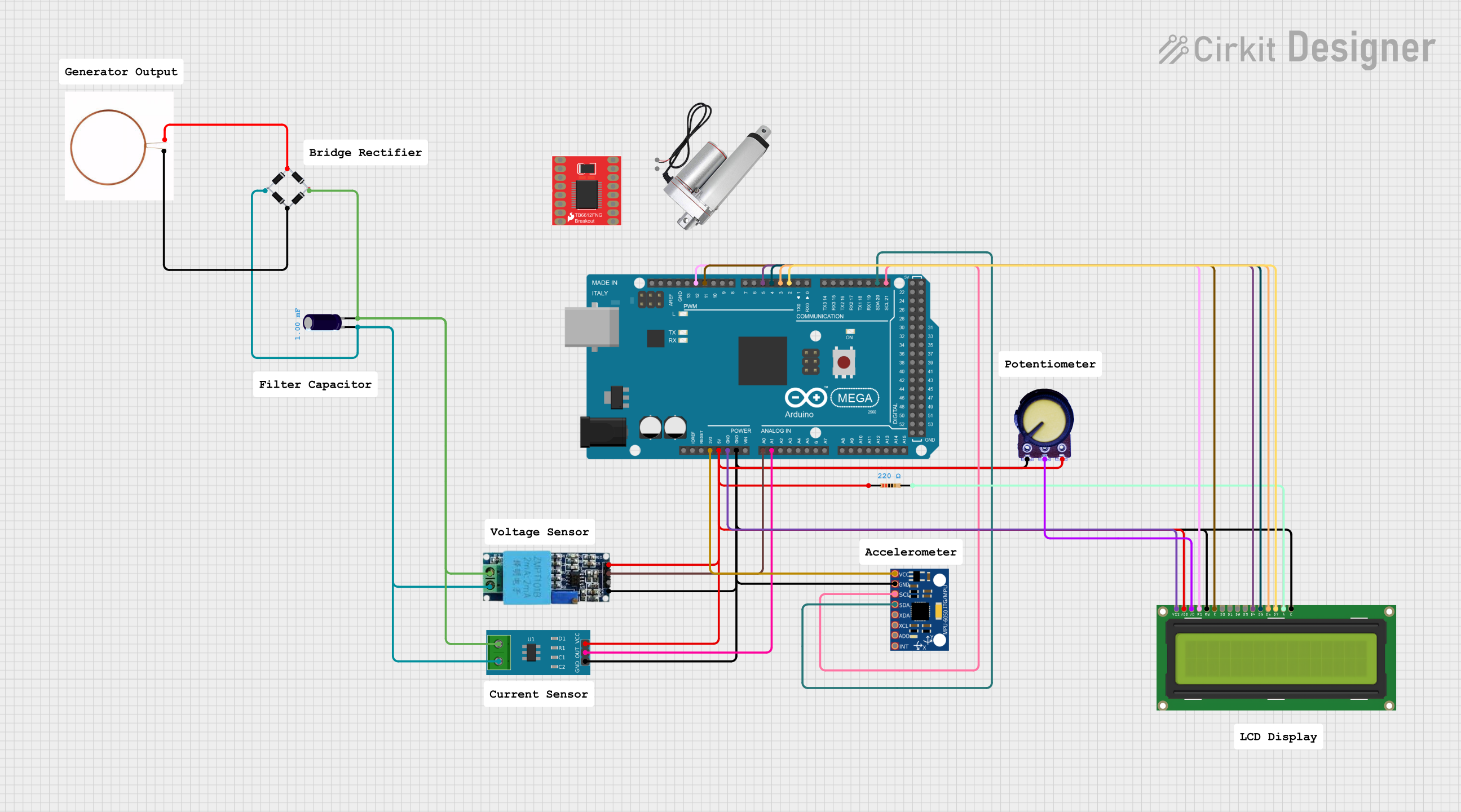
Circuit Documentation
Summary of the Circuit
This circuit appears to be designed for sensing current and voltage levels, possibly as part of a power monitoring system. It includes a bridge rectifier for converting AC to DC, an electrolytic capacitor for smoothing the output of the rectifier, a current sensor for measuring current flow, and a voltage sensor for detecting voltage levels. The Arduino Mega 2560 microcontroller is used as the central processing unit to read sensor data and control an LCD display for output. Additionally, the circuit integrates an MPU-6050 for motion tracking, a potentiometer for voltage adjustment, and a linear actuator controlled by a motor driver.
Component List
Bridge Rectifier
- Description: A device that converts an alternating current (AC) input into a direct current (DC) output.
- Pins: Source_in-, source_out-, source_out+, source_in+
Electrolytic Capacitor
- Description: A capacitor used for filtering and smoothing the DC output from the rectifier.
- Capacitance: 0.001 Farads
- Pins: -, +
Current Sensor 5A
- Description: A sensor used to measure the current flowing through a conductor.
- Pins: 1, 2, GND, OUT, VCC
Arduino Mega 2560
- Description: A microcontroller board based on the ATmega2560, used for controlling the various components in the circuit.
- Pins: IOREF, RESET, 3V3, 5V, GND, VIN, A0-A15, D0-D53, AREF, SDA, SCL
MPU-6050
- Description: A motion tracking device that contains a 3-axis gyroscope and a 3-axis accelerometer.
- Pins: VCC, GND, SCL, SDA, XDA, XCL, AD0, INT
Voltage Sensor
- Description: A sensor used to measure the voltage across two points in the circuit.
- Pins: Ground, Phase, Vcc, Out, Gnd
Copper Coil
- Description: A coil of copper wire, possibly part of an inductive sensor or transformer.
- Pins: -ve, +ve
LCD Display 16x2
- Description: A liquid crystal display capable of displaying 16 characters per line across 2 lines.
- Pins: LEDK, LEDA, DB7-DB0, E, RW, RS, VO, VDD, VSS
Resistor
- Description: A passive two-terminal electrical component that implements electrical resistance as a circuit element.
- Resistance: 220 Ohms
- Pins: pin1, pin2
Potentiometer
- Description: A three-terminal resistor with a sliding or rotating contact that forms an adjustable voltage divider.
- Pins: GND, Output, VCC
Linear Actuator
- Description: An actuator that creates motion in a straight line.
- Pins: +, -
Motor Driver 1A Dual TB6612FNG
- Description: A motor driver capable of driving a small DC motor.
- Pins: GND, B01, B02, A02, A01, VCC, VM, PWMA, AIN2, AIN1, STBY, BIN1, BIN2, PWMB
Wiring Details
Bridge Rectifier
- Source_in- connected to the +ve pin of the Copper Coil.
- Source_out- connected to the Phase pin of the Voltage Sensor, pin 2 of the Current Sensor 5A, and the - pin of the Electrolytic Capacitor.
- Source_out+ connected to the Ground pin of the Voltage Sensor, pin 1 of the Current Sensor 5A, and the + pin of the Electrolytic Capacitor.
- Source_in+ connected to the -ve pin of the Copper Coil.
Electrolytic Capacitor
-
- pin connected to the source_out- of the Bridge Rectifier.
-
- pin connected to the source_out+ of the Bridge Rectifier.
Current Sensor 5A
- Pin 1 connected to the Ground pin of the Voltage Sensor and the source_out+ of the Bridge Rectifier.
- Pin 2 connected to the Phase pin of the Voltage Sensor and the source_out- of the Bridge Rectifier.
- GND connected to the Gnd pin of the Voltage Sensor, GND pin of the Arduino Mega 2560, GND pin of the MPU-6050, LEDK and RW pins of the LCD Display 16x2, and GND pin of the Potentiometer.
- OUT connected to the A1 pin of the Arduino Mega 2560.
- VCC connected to the Vcc pin of the Voltage Sensor, pin1 of the Resistor, 5V pin of the Arduino Mega 2560, VDD pin of the LCD Display 16x2, and VCC pin of the Potentiometer.
Arduino Mega 2560
- 5V pin connected to the VCC pins of the Voltage Sensor, Current Sensor 5A, LCD Display 16x2, and Potentiometer.
- GND pin connected to the GND pins of the Voltage Sensor, Current Sensor 5A, MPU-6050, LCD Display 16x2, and Potentiometer.
- A0 pin connected to the Out pin of the Voltage Sensor.
- A1 pin connected to the OUT pin of the Current Sensor 5A.
- 3V3 pin connected to the VCC pin of the MPU-6050.
- D21/SCL pin connected to the SCL pin of the MPU-6050.
- D20/SDA pin connected to the SDA pin of the MPU-6050.
- D2 PWM pin connected to the DB7 pin of the LCD Display 16x2.
- D3 PWM pin connected to the DB6 pin of the LCD Display 16x2.
- D4 PWM pin connected to the DB5 pin of the LCD Display 16x2.
- D5 PWM pin connected to the DB4 pin of the LCD Display 16x2.
- D11 PWM pin connected to the E pin of the LCD Display 16x2.
- D12 PWM pin connected to the RS pin of the LCD Display 16x2.
MPU-6050
- VCC pin connected to the 3V3 pin of the Arduino Mega 2560.
- GND pin connected to the GND pin of the Arduino Mega 2560.
- SCL pin connected to the D21/SCL pin of the Arduino Mega 2560.
- SDA pin connected to the D20/SDA pin of the Arduino Mega 2560.
Voltage Sensor
- Ground pin connected to the source_out+ of the Bridge Rectifier and pin 1 of the Current Sensor 5A.
- Phase pin connected to the source_out- of the Bridge Rectifier and pin 2 of the Current Sensor 5A.
- Vcc pin connected to the VCC pin of the Current Sensor 5A.
- Out pin connected to the A0 pin of the Arduino Mega 2560.
- Gnd pin connected to the GND pin of the Current Sensor 5A.
LCD Display 16x2
- LEDK and RW pins connected to the GND pin of the Arduino Mega 2560.
- LEDA pin connected to pin2 of the Resistor.
- DB7 pin connected to the D2 PWM pin of the Arduino Mega 2560.
- DB6 pin connected to the D3 PWM pin of the Arduino Mega 2560.
- DB5 pin connected to the D4 PWM pin of the Arduino Mega 2560.
- DB4 pin connected to the D5 PWM pin of the Arduino Mega 2560.
- E pin connected to the D11 PWM pin of the Arduino Mega 2560.
- RS pin connected to the D12 PWM pin of the Arduino Mega 2560.
- VO pin connected to the Output pin of the Potentiometer.
- VDD pin connected to the 5V pin of the Arduino Mega 2560.
- VSS pin connected to the GND pin of the Arduino Mega 2560.
Resistor
- Pin1 connected to the VCC pin of the Current Sensor 5A.
- Pin2 connected to the LEDA pin of the LCD Display 16x2.
Potentiometer
- GND pin connected to the GND pin of the Arduino Mega 2560.
- Output pin connected to the VO pin of the LCD Display 16x2.
- VCC pin connected to the 5V pin of the Arduino Mega 2560.
Documented Code
void setup() {
  // put your setup code here, to run once:

}

void loop() {
  // put your main code here, to run repeatedly:

}
The provided code is a template for an Arduino sketch with empty setup and loop functions. The setup function is intended to initialize settings, while the loop function will contain the main code that the Arduino will run repeatedly. Additional code is required to read sensor data, control the LCD display, and interact with other components in the circuit.