
Wi-Fi Controlled Smart Target System with ESP8266 and NeoPixel Ring
View and Edit Project In Cirkit Designer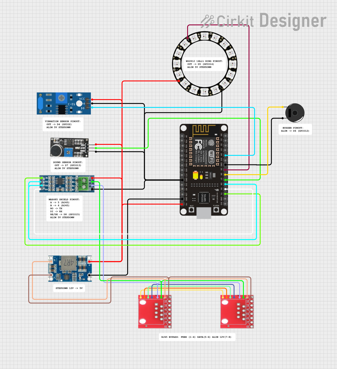
Circuit Documentation
Summary
This document provides a detailed overview of a circuit that includes various sensors, a NeoPixel ring, a piezo buzzer, an RS-485 module, and an ESP8266 NodeMCU microcontroller. The circuit is designed to detect sound and vibration, control LEDs, and communicate over a network.
Component List
Adafruit 16 NeoPixel Ring
- Description: A ring of 16 individually addressable RGB LEDs.
- Pins: VDD, IN, OUT, GND
Piezo Buzzer
- Description: A piezoelectric buzzer used for sound output.
- Pins: pin 1, pin 2
SW-420 Vibration Sensor
- Description: A sensor that detects vibrations.
- Pins: vcc, Ground, Digital output
RS-485 Module
- Description: A module for RS-485 communication.
- Pins: VCC, B, A, GND, RO, RE, DE, DI
Sound Sensor
- Description: A sensor that detects sound levels.
- Pins: 5V +, OUT, GND
Mini 560 Step Down 20-7V to 5V
- Description: A step-down voltage regulator.
- Pins: IN-, IN+, OUT-, OUT+
RJ45
- Description: An RJ45 connector for network communication.
- Pins: R1+, R1-, R2+, R2-, R3+, R3-, 5V, GND
ESP8266 NodeMCU
- Description: A microcontroller with Wi-Fi capabilities.
- Pins: D0, D1, D2, D3, D4, 3V3, GND, D5, D6, D7, D8, RX, TX, A0, RSV, SD3, SD2, SD1, CMD, SD0, CLK, EN, RST, VIN
Wiring Details
Adafruit 16 NeoPixel Ring
- VDD connected to OUT+ of Mini 560 Step Down 20-7V to 5V
- IN connected to D5 of ESP8266 NodeMCU
- GND connected to:
- Ground of SW-420 Vibration Sensor
- GND of Sound Sensor
- GND of ESP8266 NodeMCU
- GND of RS-485 Module
Piezo Buzzer
- pin 1 connected to D6 of ESP8266 NodeMCU
- pin 2 connected to GND of ESP8266 NodeMCU
SW-420 Vibration Sensor
- vcc connected to OUT+ of Mini 560 Step Down 20-7V to 5V
- Ground connected to:
- GND of Adafruit 16 NeoPixel Ring
- GND of Sound Sensor
- GND of ESP8266 NodeMCU
- GND of RS-485 Module
- Digital output connected to D4 of ESP8266 NodeMCU
RS-485 Module
- VCC connected to OUT+ of Mini 560 Step Down 20-7V to 5V
- B connected to R3- of RJ45
- A connected to R3+ of RJ45
- GND connected to:
- GND of Adafruit 16 NeoPixel Ring
- Ground of SW-420 Vibration Sensor
- GND of Sound Sensor
- GND of ESP8266 NodeMCU
- RO connected to TX of ESP8266 NodeMCU
- RE connected to D8 of ESP8266 NodeMCU
- DE connected to D8 of ESP8266 NodeMCU
- DI connected to RX of ESP8266 NodeMCU
Sound Sensor
- 5V + connected to OUT+ of Mini 560 Step Down 20-7V to 5V
- OUT connected to D7 of ESP8266 NodeMCU
- GND connected to:
- GND of Adafruit 16 NeoPixel Ring
- Ground of SW-420 Vibration Sensor
- GND of ESP8266 NodeMCU
- GND of RS-485 Module
Mini 560 Step Down 20-7V to 5V
- IN- connected to GND of RJ45
- IN+ connected to 5V of RJ45
- OUT- connected to GND of ESP8266 NodeMCU
- OUT+ connected to:
- VDD of Adafruit 16 NeoPixel Ring
- vcc of SW-420 Vibration Sensor
- 5V + of Sound Sensor
- VIN of ESP8266 NodeMCU
- VCC of RS-485 Module
RJ45
- R1+ connected to R1+ of another RJ45
- R1- connected to R1- of another RJ45
- R2+ connected to R2+ of another RJ45
- R2- connected to R2- of another RJ45
- R3+ connected to A of RS-485 Module
- R3- connected to B of RS-485 Module
- 5V connected to IN+ of Mini 560 Step Down 20-7V to 5V
- GND connected to IN- of Mini 560 Step Down 20-7V to 5V
ESP8266 NodeMCU
- D4 connected to Digital output of SW-420 Vibration Sensor
- GND connected to:
- GND of Adafruit 16 NeoPixel Ring
- Ground of SW-420 Vibration Sensor
- GND of Sound Sensor
- GND of RS-485 Module
- OUT- of Mini 560 Step Down 20-7V to 5V
- D5 connected to IN of Adafruit 16 NeoPixel Ring
- D6 connected to pin 1 of Piezo Buzzer
- D7 connected to OUT of Sound Sensor
- D8 connected to:
- RE of RS-485 Module
- DE of RS-485 Module
- RX connected to DI of RS-485 Module
- TX connected to RO of RS-485 Module
- VIN connected to OUT+ of Mini 560 Step Down 20-7V to 5V
Code Documentation
Main Code
#include <Arduino.h>
#include <FastLED.h>
#include <ESP8266WiFi.h>
#include <ESPAsyncWebServer.h>
#include <painlessMesh.h>
#include <ArduinoJson.h>
#include <ESP8266HTTPClient.h>
#include <LittleFS.h>

// Configurazione generale
#define LED_PIN 14
#define NUM_LEDS 16
#define PIEZO_PIN 12
#define SOUND_PIN 13
#define SHOCK_PIN 15
#define WIFI_SSID "ETT_SHADOWS"
#define WIFI_PASSWORD "shadowsasdlocorotondo"
#define AP_SSID "TARGET_AP"

CRGB leds[NUM_LEDS];
AsyncWebServer server(80);
painlessMesh mesh;
WiFiClient client;

// Stati
enum TargetState { CHECK, READY, WAKE, TAKEN, SLEEP };
TargetState currentState = CHECK;

unsigned long lastStateChange = 0;
const unsigned long stateTimeout = 60000; // 1 minuto
unsigned long wakeStartTime = 0;

// Bersaglio configurazioni
typedef struct {
    String id;
    String sensorType;
    String waitColor;
    String takenColor;
    int timeout;
} TargetConfig;

TargetConfig config = {
    "target_01",       // ID del bersaglio
    "sound",           // Tipo di sensore
    "#00FF00",         // Colore LED in attesa
    "#FF0000",         // Colore LED colpito
    10                 // Timeout in secondi
};

// Funzioni per rete Mesh
void meshCallback(uint32_t nodeId) {
    Serial.printf("Evento nella rete mesh: Nodo %u si è connesso o disconnesso.\n", nodeId);
}

// Funzioni Wi-Fi
void setupWiFi() {
    WiFi.begin(WIFI_SSID, WIFI_PASSWORD);
    Serial.println("Tentativo di connessione WiFi...");

    unsigned long startAttempt = millis();
    while (WiFi.status() != WL_CONNECTED && millis() - startAttempt < stateTimeout) {
        unsigned long elapsed = millis() - startAttempt;
        int ledsToLight = map(elapsed, 0