
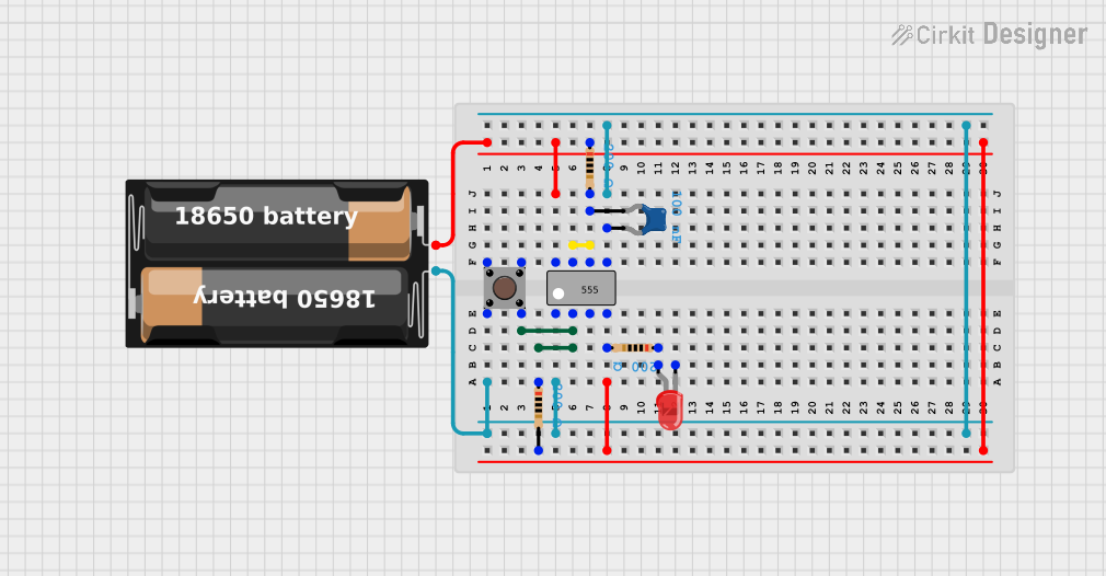
Circuit Documentation
Summary
This document provides a detailed overview of a circuit that includes resistors, a pushbutton, an LED, a ceramic capacitor, a battery case, and a 555 timer IC. The circuit is designed to demonstrate basic electronic principles, including the use of passive components, a pushbutton for user interaction, and a 555 timer for generating pulses.
Component List
Resistor
- Description: A passive electrical component that implements electrical resistance as a circuit element.
- Properties:
- Resistance: 200 Ohms
Pushbutton
- Description: A simple switch mechanism for controlling some aspect of a machine or a process.
- Properties: None
LED: Two Pin (red)
- Description: A light-emitting diode that emits red light when current flows through it.
- Properties: None
Ceramic Capacitor
- Description: A capacitor that uses a ceramic material as the dielectric.
- Properties:
- Capacitance: 0.0000001 Farads
Battery Case
- Description: A holder for batteries to provide power to the circuit.
- Properties: None
555 Timer IC
- Description: A highly stable device for generating accurate time delays or oscillation.
- Properties: None
Wiring Details
Resistor 1
- Pins:
- pin1: Connected to the positive terminal of the battery case and the VCC pin of the 555 timer IC.
- pin2: Connected to the DIS pin of the 555 timer IC.
Resistor 2
- Pins:
- pin1: Connected to the anode of the LED.
- pin2: Connected to the positive terminal of the battery case and the VCC pin of the 555 timer IC.
Resistor 3
- Pins:
- pin1: Connected to the positive terminal of the battery case and the VCC pin of the 555 timer IC.
- pin2: Connected to the DIS pin of the 555 timer IC.
Pushbutton
- Pins:
- Pin 1 (in): Not connected.
- Pin 2 (in): Connected to the negative terminal of the battery case, the GND pin of the 555 timer IC, the pin1 of the ceramic capacitor, and the CTRL pin of the 555 timer IC.
- Pin 3 (out): Not connected.
- Pin 4 (out): Connected to pin1 of Resistor 3 and the TRIG pin of the 555 timer IC.
LED: Two Pin (red)
- Pins:
- Cathode: Not connected.
- Anode: Connected to pin1 of Resistor 2.
Ceramic Capacitor
- Pins:
- pin0: Connected to the DIS pin of the 555 timer IC.
- pin1: Connected to the negative terminal of the battery case, the GND pin of the 555 timer IC, the Pin 2 (in) of the pushbutton, and the CTRL pin of the 555 timer IC.
Battery Case
- Pins:
- +: Connected to pin1 of Resistor 1, pin1 of Resistor 2, pin1 of Resistor 3, the VCC pin of the 555 timer IC, and the ~RESET pin of the 555 timer IC.
- -: Connected to Pin 2 (in) of the pushbutton, the GND pin of the 555 timer IC, pin1 of the ceramic capacitor, and the CTRL pin of the 555 timer IC.
555 Timer IC
- Pins:
- GND: Connected to the negative terminal of the battery case, Pin 2 (in) of the pushbutton, pin1 of the ceramic capacitor, and the CTRL pin of the 555 timer IC.
- TRIG: Connected to Pin 4 (out) of the pushbutton and pin1 of Resistor 3.
- OUT: Not connected.
- ~RESET: Connected to the positive terminal of the battery case.
- VCC: Connected to the positive terminal of the battery case and pin1 of Resistor 1.
- DIS: Connected to pin2 of Resistor 1, pin0 of the ceramic capacitor, and the THR pin of the 555 timer IC.
- THR: Connected to the DIS pin of the 555 timer IC.
- CTRL: Connected to the negative terminal of the battery case, Pin 2 (in) of the pushbutton, the GND pin of the 555 timer IC, and pin1 of the ceramic capacitor.
Code
No microcontroller code is provided for this circuit.