
Arduino UNO Controlled 8-Channel Relay with 12V LED Indicators
View and Edit Project In Cirkit Designer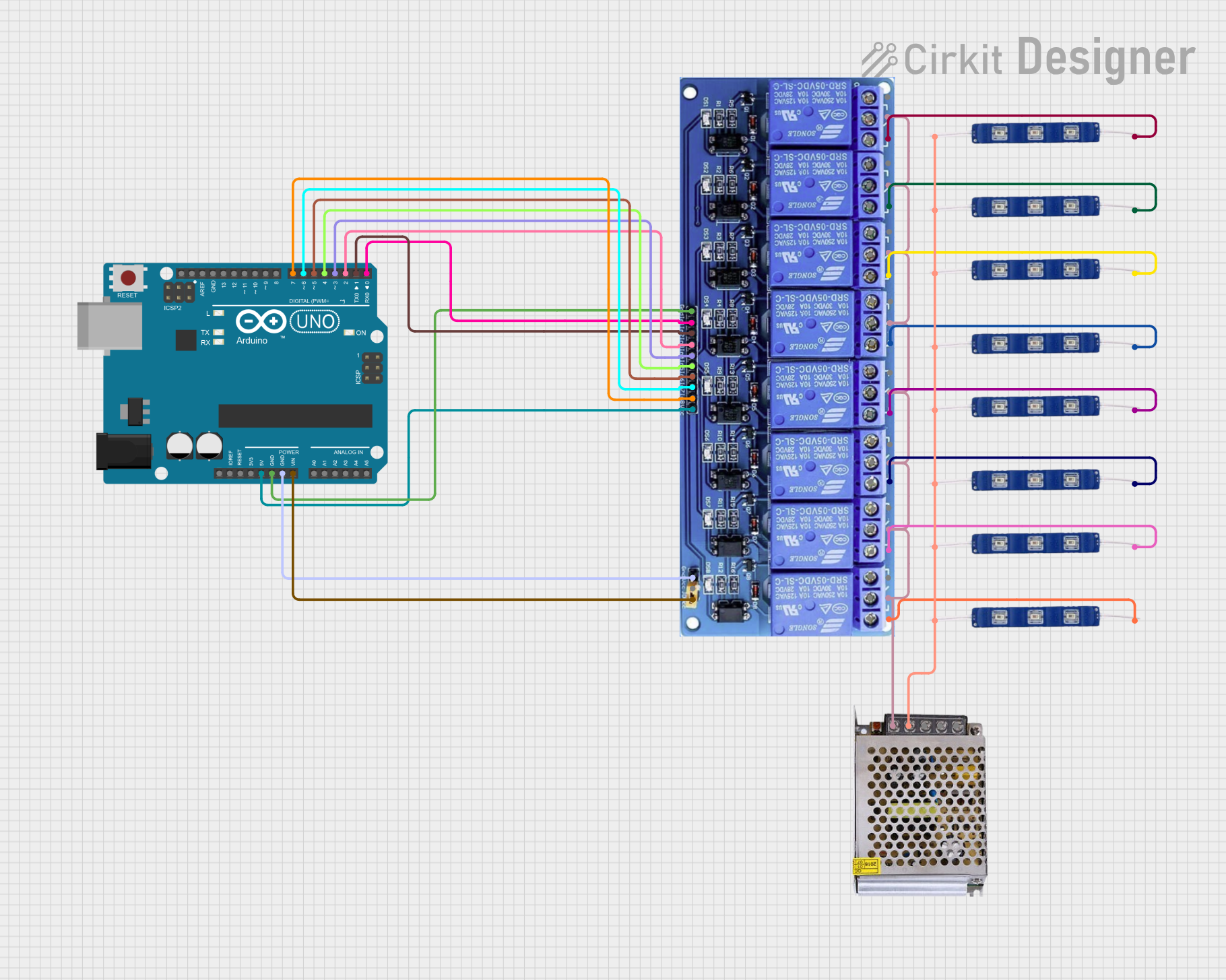
Circuit Documentation
Summary
This circuit involves an Arduino UNO microcontroller controlling an 8-channel relay module, which in turn controls multiple 12V Blue LEDs. The circuit is powered by a 12V 5A power supply. The Arduino UNO is programmed to randomly turn the relays on and off, and also to create a fading effect on an LED connected to a PWM pin.
Component List
Arduino UNO
- Description: A microcontroller board based on the ATmega328P.
- Pins: UNUSED, IOREF, Reset, 3.3V, 5V, GND, Vin, A0, A1, A2, A3, A4, A5, SCL, SDA, AREF, D13, D12, D11, D10, D9, D8, D7, D6, D5, D4, D3, D2, D1, D0
8 Channel Relay JD-VCC
- Description: A relay module that allows control of high voltage devices with low voltage signals.
- Pins: JD-VCC, VCC, GND, In8, In7, In6, In5, In4, In3, In2, In1, In1_NC, IN1_COM, IN1_NO, IN2_NC, IN2_COM, IN2_NO, IN3_NC, IN3_COM, IN3_NO, IN4_NC, IN4_COM, IN4_NO, IN5_NC, IN5_COM, IN5_NO, IN6_NC, IN6_COM, IN6_NO, IN7_NC, IN7_COM, IN7_NO, IN8_NC, IN8_COM, IN8_NO
12V Blue LED
- Description: A blue LED that operates at 12V.
- Pins: GND, VCC
POWER SUPPLY 12V 5AMP
- Description: A power supply that provides 12V DC at up to 5A.
- Pins: 220V Positive Pole (AC), 220V Negative Pole (AC), GND, GND (DC), 12V-24V Output (DC)
Wiring Details
Arduino UNO
- 5V connected to VCC of 8 Channel Relay JD-VCC
- GND connected to GND of 8 Channel Relay JD-VCC
- Vin connected to JD-VCC of 8 Channel Relay JD-VCC
- D7 connected to In8 of 8 Channel Relay JD-VCC
- D6 connected to In7 of 8 Channel Relay JD-VCC
- D5 connected to In6 of 8 Channel Relay JD-VCC
- D4 connected to In5 of 8 Channel Relay JD-VCC
- D3 connected to In4 of 8 Channel Relay JD-VCC
- D2 connected to In3 of 8 Channel Relay JD-VCC
- D1 connected to In2 of 8 Channel Relay JD-VCC
- D0 connected to In1 of 8 Channel Relay JD-VCC
8 Channel Relay JD-VCC
- VCC connected to 5V of Arduino UNO
- GND connected to GND of Arduino UNO
- JD-VCC connected to Vin of Arduino UNO
- In8 connected to D7 of Arduino UNO
- In7 connected to D6 of Arduino UNO
- In6 connected to D5 of Arduino UNO
- In5 connected to D4 of Arduino UNO
- In4 connected to D3 of Arduino UNO
- In3 connected to D2 of Arduino UNO
- In2 connected to D1 of Arduino UNO
- In1 connected to D0 of Arduino UNO
- IN1_COM connected to 12V-24V Output (DC) of POWER SUPPLY 12V 5AMP
- IN2_COM connected to 12V-24V Output (DC) of POWER SUPPLY 12V 5AMP
- IN3_COM connected to 12V-24V Output (DC) of POWER SUPPLY 12V 5AMP
- IN4_COM connected to 12V-24V Output (DC) of POWER SUPPLY 12V 5AMP
- IN5_COM connected to 12V-24V Output (DC) of POWER SUPPLY 12V 5AMP
- IN6_COM connected to 12V-24V Output (DC) of POWER SUPPLY 12V 5AMP
- IN7_COM connected to 12V-24V Output (DC) of POWER SUPPLY 12V 5AMP
- IN8_COM connected to 12V-24V Output (DC) of POWER SUPPLY 12V 5AMP
- IN1_NO connected to VCC of 12V Blue LED
- IN2_NO connected to VCC of 12V Blue LED
- IN3_NO connected to VCC of 12V Blue LED
- IN4_NO connected to VCC of 12V Blue LED
- IN5_NO connected to VCC of 12V Blue LED
- IN6_NO connected to VCC of 12V Blue LED
- IN7_NO connected to VCC of 12V Blue LED
- IN8_NO connected to VCC of 12V Blue LED
12V Blue LED
- VCC connected to IN1_NO of 8 Channel Relay JD-VCC
- VCC connected to IN2_NO of 8 Channel Relay JD-VCC
- VCC connected to IN3_NO of 8 Channel Relay JD-VCC
- VCC connected to IN4_NO of 8 Channel Relay JD-VCC
- VCC connected to IN5_NO of 8 Channel Relay JD-VCC
- VCC connected to IN6_NO of 8 Channel Relay JD-VCC
- VCC connected to IN7_NO of 8 Channel Relay JD-VCC
- VCC connected to IN8_NO of 8 Channel Relay JD-VCC
- GND connected to GND (DC) of POWER SUPPLY 12V 5AMP
POWER SUPPLY 12V 5AMP
- 12V-24V Output (DC) connected to IN1_COM of 8 Channel Relay JD-VCC
- 12V-24V Output (DC) connected to IN2_COM of 8 Channel Relay JD-VCC
- 12V-24V Output (DC) connected to IN3_COM of 8 Channel Relay JD-VCC
- 12V-24V Output (DC) connected to IN4_COM of 8 Channel Relay JD-VCC
- 12V-24V Output (DC) connected to IN5_COM of 8 Channel Relay JD-VCC
- 12V-24V Output (DC) connected to IN6_COM of 8 Channel Relay JD-VCC
- 12V-24V Output (DC) connected to IN7_COM of 8 Channel Relay JD-VCC
- 12V-24V Output (DC) connected to IN8_COM of 8 Channel Relay JD-VCC
- GND (DC) connected to GND of 12V Blue LED
Code Documentation
// Define the pins for the 8 relay channels
const int relayPins[] = {2, 3, 4, 5, 6, 7, 8, 9}; // Change pins as needed
const int numRelays = 8; // Total number of relays

// Define LED pin for fade effect
const int ledPin = 10;  // PWM pin to control LED brightness

void setup() {
  // Initialize relay pins as output
  for (int i = 0; i < numRelays; i++) {
    pinMode(relayPins[i], OUTPUT);
    digitalWrite(relayPins[i], LOW); // Make sure relays are off initially
  }

  // Initialize the LED pin as output
  pinMode(ledPin, OUTPUT);
}

void loop() {
  // Randomly turn relays on and off
  int relayIndex = random(0, numRelays);  // Random relay index (0 to 7)
  int state = random(0, 2);  // Random state (0 = OFF, 1 = ON)

  digitalWrite(relayPins[relayIndex], state == 1 ? HIGH : LOW);  // Turn relay on/off

  // Create a fading LED effect (smooth on and off)
  for (int brightness = 0; brightness <= 255; brightness