
Arduino Mega 2560 Bluetooth-Controlled LED Matrix Display with Servo Motor
View and Edit Project In Cirkit Designer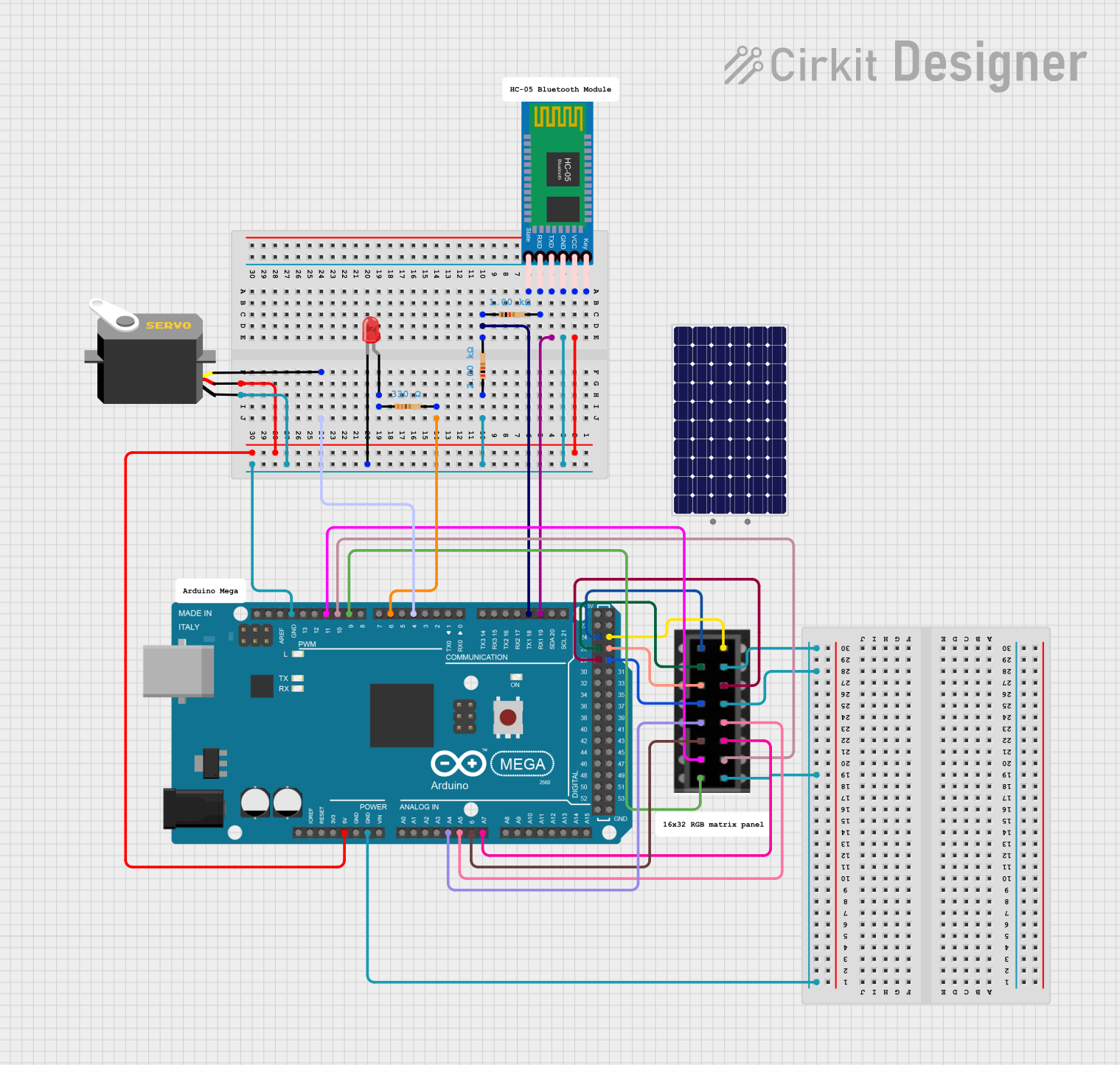
Circuit Documentation
Summary
This circuit involves an Arduino Mega 2560 microcontroller interfacing with various components including an HC-05 Bluetooth module, a 64x32 LED matrix, a servo motor, and a red LED. The circuit also includes several resistors to manage current flow. The Arduino Mega 2560 is programmed to control these components.
Component List
Arduino Mega 2560
- Description: A microcontroller board based on the ATmega2560.
- Pins: IOREF, RESET, 3V3, 5V, GND, VIN, A0-A15, D0-D53, AREF, SDA, SCL
Resistor (1000 Ohms)
- Description: A resistor with a resistance of 1000 Ohms.
- Pins: pin1, pin2
- Properties: Resistance: 1000 Ohms
Resistor (330 Ohms)
- Description: A resistor with a resistance of 330 Ohms.
- Pins: pin1, pin2
- Properties: Resistance: 330 Ohms
Resistor (2000 Ohms)
- Description: A resistor with a resistance of 2000 Ohms.
- Pins: pin1, pin2
- Properties: Resistance: 2000 Ohms
LED Matrix 64x32
- Description: A 64x32 LED matrix display.
- Pins: R1, B1, R2, B2, A, C, CLK, OE, G1, GND, G2, B, D, LAT
HC-05 Bluetooth Module
- Description: A Bluetooth module for wireless communication.
- Pins: Key, VCC, GND, TXD, RXD, State
LED: Two Pin (red)
- Description: A red LED with two pins.
- Pins: cathode, anode
Servo
- Description: A servo motor for precise control of angular position.
- Pins: gnd, vcc, pulse
Solar Panel
- Description: A solar panel for generating electrical power.
- Pins: +, -
Wiring Details
Arduino Mega 2560
- 5V: Connected to VCC of HC-05 Bluetooth Module and VCC of Servo.
- GND: Connected to GND of HC-05 Bluetooth Module, cathode of LED, pin1 of 2000 Ohms Resistor, GND of Servo, GND of LED Matrix 64x32.
- D19/RX1: Connected to TXD of HC-05 Bluetooth Module.
- D18/TX1: Connected to pin1 of 1000 Ohms Resistor.
- D6 PWM: Connected to pin2 of 330 Ohms Resistor.
- D4 PWM: Connected to pulse of Servo.
- A4: Connected to A of LED Matrix 64x32.
- A5: Connected to B of LED Matrix 64x32.
- A6: Connected to C of LED Matrix 64x32.
- A7: Connected to D of LED Matrix 64x32.
- D9 PWM: Connected to OE of LED Matrix 64x32.
- D10 PWM: Connected to LAT of LED Matrix 64x32.
- D11 PWM: Connected to CLK of LED Matrix 64x32.
- D28: Connected to G2 of LED Matrix 64x32.
- D26: Connected to B1 of LED Matrix 64x32.
- D24: Connected to R1 of LED Matrix 64x32.
- D29: Connected to B2 of LED Matrix 64x32.
- D27: Connected to R2 of LED Matrix 64x32.
- D25: Connected to G1 of LED Matrix 64x32.
HC-05 Bluetooth Module
- VCC: Connected to 5V of Arduino Mega 2560.
- GND: Connected to GND of Arduino Mega 2560.
- TXD: Connected to D19/RX1 of Arduino Mega 2560.
- RXD: Connected to pin2 of 1000 Ohms Resistor.
Resistor (1000 Ohms)
- pin1: Connected to D18/TX1 of Arduino Mega 2560.
- pin2: Connected to RXD of HC-05 Bluetooth Module.
Resistor (330 Ohms)
- pin1: Connected to anode of LED.
- pin2: Connected to D6 PWM of Arduino Mega 2560.
Resistor (2000 Ohms)
- pin1: Connected to GND of Arduino Mega 2560.
- pin2: Connected to cathode of LED.
LED Matrix 64x32
- GND: Connected to GND of Arduino Mega 2560.
- A: Connected to A4 of Arduino Mega 2560.
- B: Connected to A5 of Arduino Mega 2560.
- C: Connected to A6 of Arduino Mega 2560.
- D: Connected to A7 of Arduino Mega 2560.
- OE: Connected to D9 PWM of Arduino Mega 2560.
- LAT: Connected to D10 PWM of Arduino Mega 2560.
- CLK: Connected to D11 PWM of Arduino Mega 2560.
- G2: Connected to D28 of Arduino Mega 2560.
- B1: Connected to D26 of Arduino Mega 2560.
- R1: Connected to D24 of Arduino Mega 2560.
- B2: Connected to D29 of Arduino Mega 2560.
- R2: Connected to D27 of Arduino Mega 2560.
- G1: Connected to D25 of Arduino Mega 2560.
LED: Two Pin (red)
- cathode: Connected to GND of Arduino Mega 2560.
- anode: Connected to pin1 of 330 Ohms Resistor.
Servo
- gnd: Connected to GND of Arduino Mega 2560.
- vcc: Connected to 5V of Arduino Mega 2560.
- pulse: Connected to D4 PWM of Arduino Mega 2560.
Documented Code
Arduino Mega 2560 Code
#define LED 6

void setup()
{
  // put your setup code here, to run once:
   pinMode(LED, OUTPUT);
}

void loop() {
  // put your main code here, to run repeatedly:
    digitalWrite(LED, HIGH);
}
This code sets up pin 6 as an output and continuously sets it to HIGH, turning on the LED connected to pin 6.