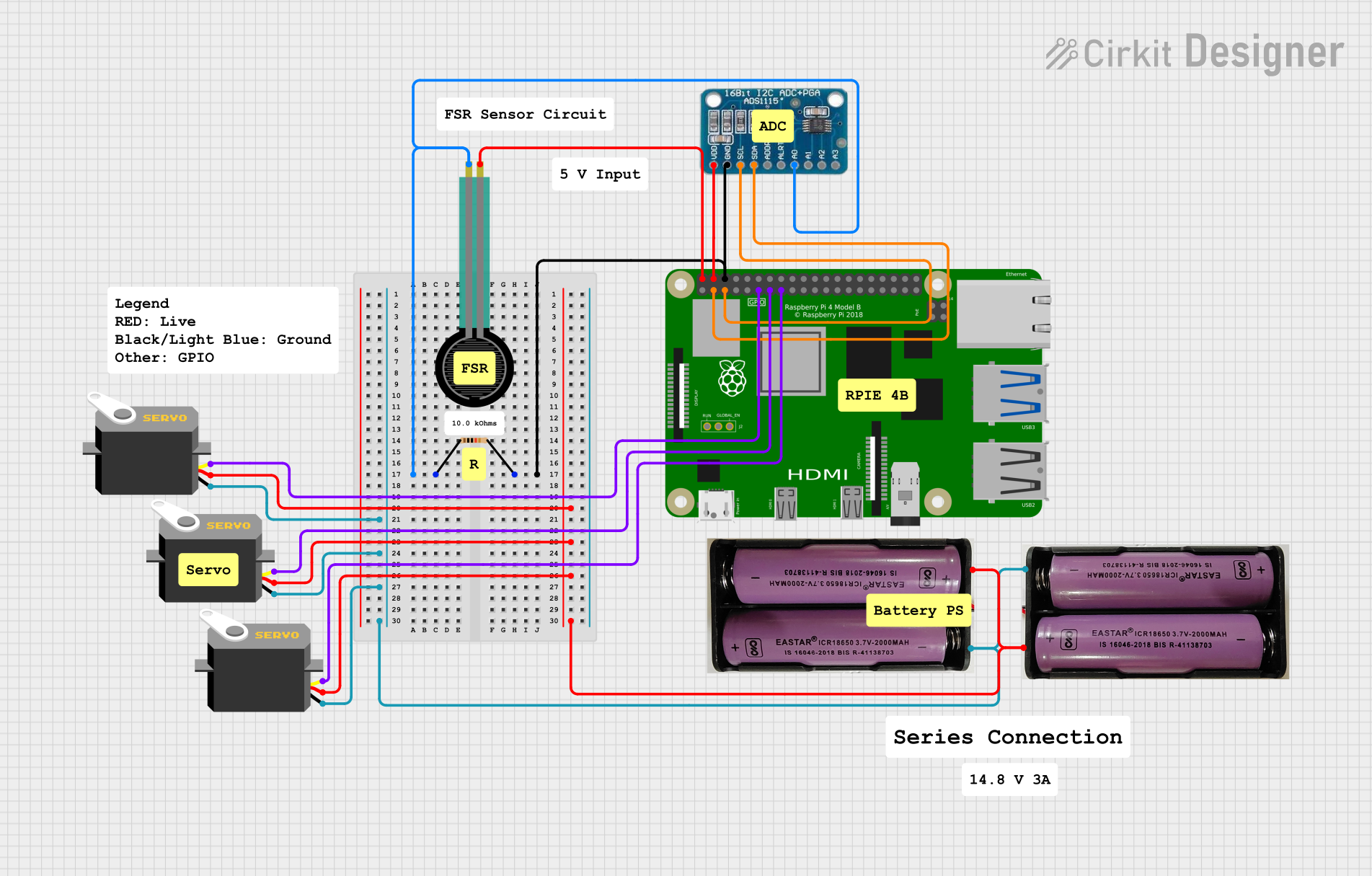
Raspberry Pi-Controlled Force-Sensitive Servo System with ADS1115 ADC

Circuit Documentation
Summary
The circuit in question appears to be designed for sensing force via a Force Sensing Resistor (FSR) and controlling multiple servo motors based on the sensed force. The circuit uses an ADS1115 analog-to-digital converter (ADC) to read the analog signal from the FSR and communicate the digital data to a Raspberry Pi 4B microcontroller via I2C communication. The Raspberry Pi then likely processes this data to control the position of the servo motors. Power is supplied to the servos and the ADS1115 by two separate 7.4V power sources.
Component List
ADS1115
- Description: A precision, low-power, 16-bit ADC with I2C interface.
- Pins: VDD, GND, SCL, SDA, ADDR, ALRT, A0, A1, A2, A3
7.4V Battery
- Description: A power source for the circuit.
- Pins: + (positive terminal), - (negative terminal)
Servo Motor
- Description: An actuator that can be precisely controlled for angular position.
- Pins: gnd (ground), vcc (power supply), pulse (control signal)
Force Sensing Resistor (FSR)
- Description: A sensor that changes its resistance based on the force applied to it.
- Pins: pin 0, pin 1
Resistor (10k Ohms)
- Description: A passive two-terminal electrical component that implements electrical resistance as a circuit element.
- Pins: pin1, pin2
- Properties: Resistance value of 10,000 Ohms
Raspberry Pi 4B
- Description: A small, powerful computer and development board that can be used for a variety of applications.
- Pins: Multiple GPIO pins, power, and ground pins.
Wiring Details
ADS1115
- VDD connected to Raspberry Pi 4B 5V
- GND connected to Resistor pin2 and Raspberry Pi 4B GND
- SCL connected to Raspberry Pi 4B GPIO3
- SDA connected to Raspberry Pi 4B GPIO2
- A0 connected to Resistor pin1 and Force Sensing Resistor pin 1
7.4V Battery
- "+" connected to all Servo vcc pins
- "-" connected to all Servo gnd pins
Servo Motor
- gnd connected to 7.4V Battery "-"
- vcc connected to 7.4V Battery "+"
- pulse connected to Raspberry Pi GPIO pins (GPIO17, GPIO27, GPIO22)
Force Sensing Resistor (FSR)
- pin 0 connected to Raspberry Pi 4B 5V
- pin 1 connected to Resistor pin1 and ADS1115 A0
Resistor (10k Ohms)
- pin1 connected to Force Sensing Resistor pin 1 and ADS1115 A0
- pin2 connected to Raspberry Pi 4B GND and ADS1115 GND
Raspberry Pi 4B
- 5V connected to ADS1115 VDD and Force Sensing Resistor pin 0
- GND connected to Resistor pin2 and ADS1115 GND
- GPIO2 connected to ADS1115 SDA
- GPIO3 connected to ADS1115 SCL
- GPIO17 connected to Servo (instance 1) pulse
- GPIO27 connected to Servo (instance 2) pulse
- GPIO22 connected to Servo (instance 3) pulse
Documented Code
No code has been provided for the microcontroller (Raspberry Pi 4B). The expected code would handle initializing the I2C communication with the ADS1115, reading the digital value corresponding to the force sensed by the FSR, and then controlling the servo motors based on the force reading. The code would also include setting up the GPIO pins for servo control and possibly implementing a control algorithm to determine the servo positions.