
Arduino and ESP32-CAM Controlled Robotic System with Battery Power
View and Edit Project In Cirkit Designer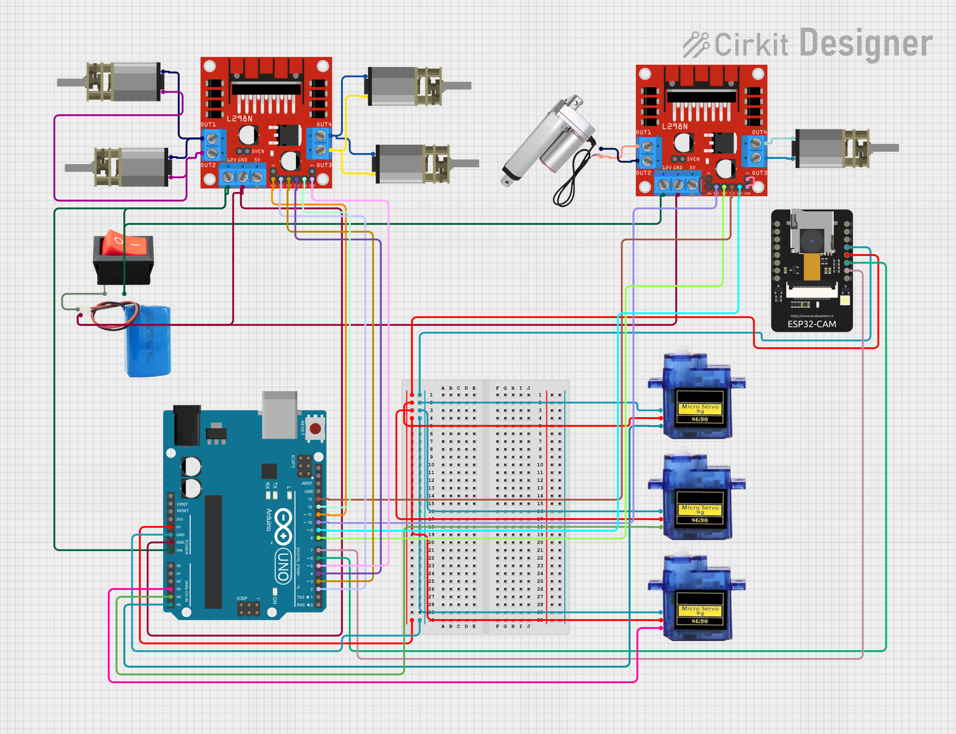
Circuit Documentation
Summary
This circuit involves an Arduino UNO microcontroller, an ESP32-CAM module, multiple DC Mini Metal Gear Motors, a Linear Actuator, Micro Servo Motors, L298N DC Motor Drivers, a Rocker Switch, and a 5V Battery. The circuit is designed to control various motors and servos, with the Arduino UNO and ESP32-CAM providing the necessary control signals.
Component List
Arduino UNO
- Description: A microcontroller board based on the ATmega328P.
- Pins: UNUSED, IOREF, Reset, 3.3V, 5V, GND, Vin, A0, A1, A2, A3, A4, A5, SCL, SDA, AREF, D13, D12, D11, D10, D9, D8, D7, D6, D5, D4, D3, D2, D1, D0
DC Mini Metal Gear Motor
- Description: A small DC motor with metal gears.
- Pins: IN1, IN2
Linear Actuator
- Description: A device that creates motion in a straight line.
- Pins: +, -
Micro Servo 9G
- Description: A small servo motor used for precise control of angular position.
- Pins: GND, +5V, PWM
ESP32 - CAM
- Description: A Wi-Fi and Bluetooth module with a built-in camera.
- Pins: 5V, GND, IO12, IO13, IO15, IO14, IO2, IO4, VOT, VOR, VCC, IO0, IO16, 3V3
Rocker Switch
- Description: A switch that controls the flow of electricity in a circuit.
- Pins: output, input
5V Battery
- Description: A battery providing a 5V power supply.
- Pins: positive, negative
L298N DC Motor Driver
- Description: A dual H-Bridge motor driver.
- Pins: OUT1, OUT2, 12V, GND, 5V, OUT3, OUT4, 5V-ENA-JMP-I, 5V-ENA-JMP-O, +5V-J1, +5V-J2, ENA, IN1, IN2, IN3, IN4, ENB
Wiring Details
Arduino UNO
- 5V connected to:
- ESP32 - CAM (VCC)
- Micro Servo 9G (+5V)
- GND connected to:
- ESP32 - CAM (GND)
- Micro Servo 9G (GND)
- L298N DC Motor Driver (GND)
- 5V Battery (negative)
- Vin connected to:
- L298N DC Motor Driver (12V)
- Rocker Switch (output)
- A3 connected to:
- Micro Servo 9G (PWM)
- A4 connected to:
- Micro Servo 9G (PWM)
- A5 connected to:
- Micro Servo 9G (PWM)
- D13 connected to:
- L298N DC Motor Driver (IN3)
- D12 connected to:
- L298N DC Motor Driver (IN4)
- D11 connected to:
- L298N DC Motor Driver (ENA)
- D10 connected to:
- L298N DC Motor Driver (IN1)
- D9 connected to:
- L298N DC Motor Driver (IN4)
- D8 connected to:
- L298N DC Motor Driver (IN2)
- D7 connected to:
- ESP32 - CAM (VOT)
- D6 connected to:
- ESP32 - CAM (VOR)
- D5 connected to:
- L298N DC Motor Driver (ENB)
- D4 connected to:
- L298N DC Motor Driver (IN3)
- D3 connected to:
- L298N DC Motor Driver (IN2)
- D2 connected to:
- L298N DC Motor Driver (IN1)
DC Mini Metal Gear Motor
- IN1 connected to:
- L298N DC Motor Driver (OUT2)
- L298N DC Motor Driver (OUT4)
- IN2 connected to:
- L298N DC Motor Driver (OUT1)
- L298N DC Motor Driver (OUT3)
Linear Actuator
- + connected to:
- L298N DC Motor Driver (OUT1)
- - connected to:
- L298N DC Motor Driver (OUT2)
Micro Servo 9G
- GND connected to:
- Arduino UNO (GND)
- +5V connected to:
- Arduino UNO (5V)
- PWM connected to:
- Arduino UNO (A3)
- Arduino UNO (A4)
- Arduino UNO (A5)
ESP32 - CAM
- VCC connected to:
- Arduino UNO (5V)
- GND connected to:
- Arduino UNO (GND)
- VOT connected to:
- Arduino UNO (D7)
- VOR connected to:
- Arduino UNO (D6)
Rocker Switch
- output connected to:
- Arduino UNO (Vin)
- input connected to:
- 5V Battery (positive)
5V Battery
- positive connected to:
- Rocker Switch (input)
- negative connected to:
- Arduino UNO (GND)
L298N DC Motor Driver
- GND connected to:
- Arduino UNO (GND)
- 5V Battery (negative)
- 12V connected to:
- Arduino UNO (Vin)
- Rocker Switch (output)
- OUT1 connected to:
- DC Mini Metal Gear Motor (IN2)
- Linear Actuator (+)
- OUT2 connected to:
- DC Mini Metal Gear Motor (IN1)
- Linear Actuator (-)
- OUT3 connected to:
- DC Mini Metal Gear Motor (IN2)
- OUT4 connected to:
- DC Mini Metal Gear Motor (IN1)
- ENA connected to:
- Arduino UNO (D11)
- ENB connected to:
- Arduino UNO (D5)
- IN1 connected to:
- Arduino UNO (D10)
- Arduino UNO (D2)
- IN2 connected to:
- Arduino UNO (D8)
- Arduino UNO (D3)
- IN3 connected to:
- Arduino UNO (D13)
- Arduino UNO (D4)
- IN4 connected to:
- Arduino UNO (D12)
- Arduino UNO (D9)
Documented Code
Arduino UNO Code (sketch.ino)
void setup() {
  // put your setup code here, to run once:

}

void loop() {
  // put your main code here, to run repeatedly:

}
Additional Documentation (documentation.txt)
This documentation provides a comprehensive overview of the circuit, including a summary, detailed component list, wiring details, and the code used in the microcontroller.