
Arduino UNO and Bluetooth HC-06 Controlled Smart Home Automation System
View and Edit Project In Cirkit Designer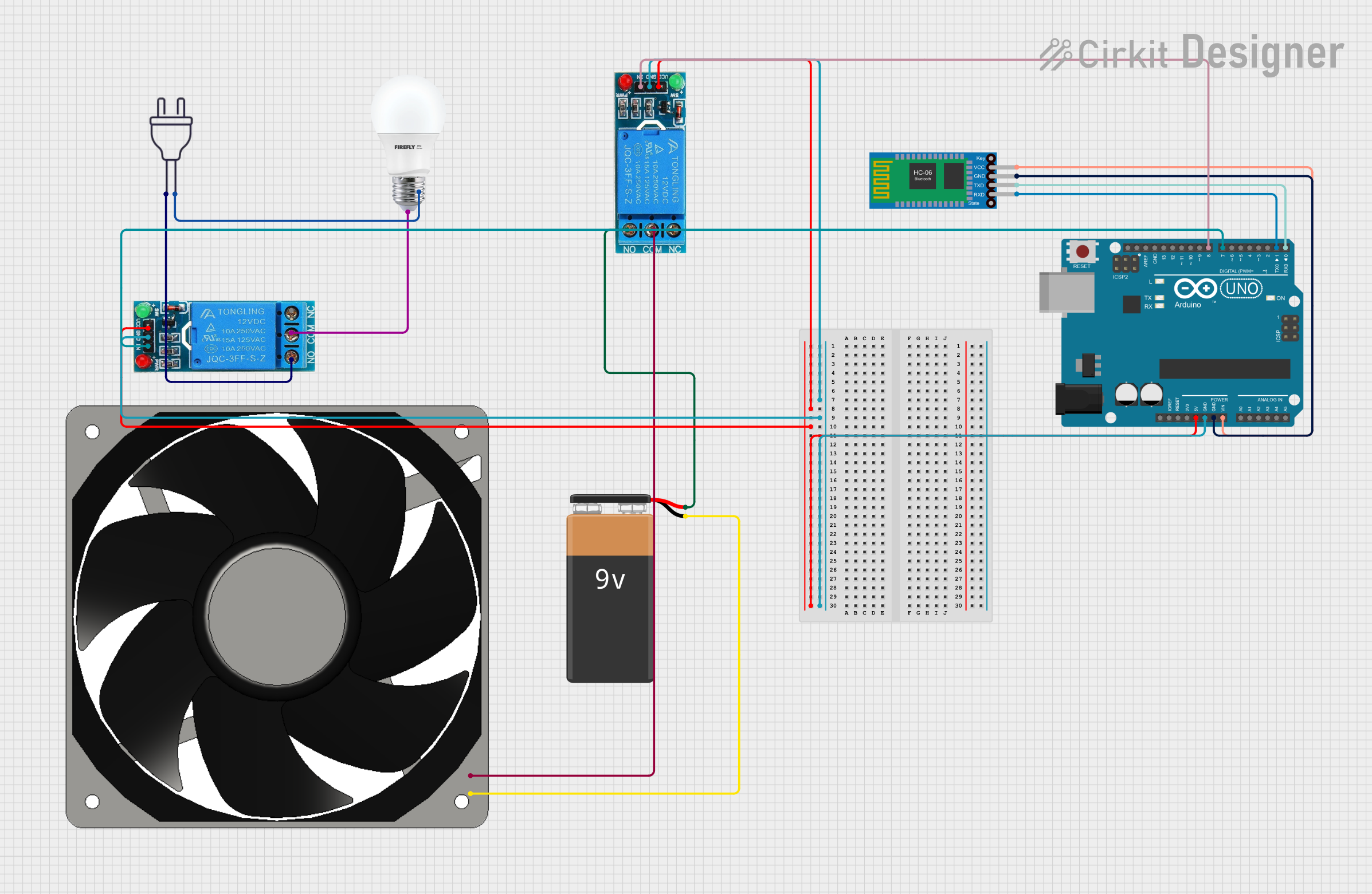
Circuit Documentation
Summary
This circuit integrates an Arduino UNO microcontroller, a Bluetooth HC-06 module, a 9V battery, a 120V fan, two 12V single-channel relays, a bulb, and a 220V power source. The Arduino UNO controls the relays based on commands received via Bluetooth, which in turn control the fan and the bulb.
Component List
Bluetooth HC-06
- Description: Bluetooth module for wireless communication.
- Pins: VCC, GND, TXD, RXD
Arduino UNO
- Description: Microcontroller board based on the ATmega328P.
- Pins: UNUSED, IOREF, Reset, 3.3V, 5V, GND, Vin, A0, A1, A2, A3, A4, A5, SCL, SDA, AREF, D13, D12, D11, D10, D9, D8, D7, D6, D5, D4, D3, D2, D1, D0
9V Battery
- Description: Power source for the fan.
- Pins: -, +
120V Fan
- Description: Fan operating at 12V.
- Pins: 12V+, GND
12V Single Channel Relay (Relay 1)
- Description: Relay for switching the fan.
- Pins: NC, COM, NO, IN, GND, VCC
12V Single Channel Relay (Relay 2)
- Description: Relay for switching the bulb.
- Pins: NC, COM, NO, IN, GND, VCC
Bulb
- Description: Light bulb.
- Pins: +, -
Power 220V
- Description: 220V power source for the bulb.
- Pins: hot wire, neutral wire
Wiring Details
Bluetooth HC-06
- VCC connected to Vin of Arduino UNO
- GND connected to GND of Arduino UNO
- TXD connected to D0 of Arduino UNO
- RXD connected to D1 of Arduino UNO
Arduino UNO
- Vin connected to VCC of Bluetooth HC-06
- GND connected to GND of Bluetooth HC-06
- D0 connected to TXD of Bluetooth HC-06
- D1 connected to RXD of Bluetooth HC-06
- GND connected to GND of Relay 1 and Relay 2
- 5V connected to VCC of Relay 1 and Relay 2
- D8 connected to IN of Relay 1
- D7 connected to IN of Relay 2
9V Battery
- - connected to GND of 120V Fan
- + connected to NO of Relay 1
120V Fan
- 12V+ connected to COM of Relay 1
- GND connected to - of 9V Battery
12V Single Channel Relay (Relay 1)
- GND connected to GND of Arduino UNO
- VCC connected to 5V of Arduino UNO
- IN connected to D8 of Arduino UNO
- NO connected to + of 9V Battery
- COM connected to 12V+ of 120V Fan
12V Single Channel Relay (Relay 2)
- GND connected to GND of Arduino UNO
- VCC connected to 5V of Arduino UNO
- IN connected to D7 of Arduino UNO
- NO connected to hot wire of Power 220V
- COM connected to + of Bulb
Bulb
- + connected to COM of Relay 2
- - connected to neutral wire of Power 220V
Power 220V
- hot wire connected to NO of Relay 2
- neutral wire connected to - of Bulb
Code Documentation
Arduino UNO Code
int fanrelay = 8;
int lightrelay = 7;
char sms;

void setup() {
  pinMode(fanrelay, OUTPUT);
  pinMode(lightrelay, OUTPUT);

  digitalWrite(fanrelay, HIGH);
  digitalWrite(lightrelay, HIGH);
  Serial.begin(9600);
}

void loop() {
  if (Serial.available() != 0) {
    sms = Serial.read();
  }
  if (sms == '1') {
    digitalWrite(fanrelay, LOW);
  }
  if (sms == '2') {
    digitalWrite(fanrelay, HIGH);
  }
  if (sms == 'a') {
    digitalWrite(lightrelay, LOW);
  }
  if (sms == 'b') {
    digitalWrite(lightrelay, HIGH);
  }
}
This code initializes the relays connected to pins 8 and 7 of the Arduino UNO. It reads commands from the Bluetooth module via the serial port and controls the relays accordingly. Commands '1' and '2' control the fan relay, while commands 'a' and 'b' control the light relay.